Starter Signal Circuit [12/2019 - 10/2022]: Procedure
- CHECK CRANKING
- Engine start and check that the engine cranks.
Result
Result Proceed to Engine cranks A Engine does not crank B
Result:
B
See step 7
Result:
A
See step 2
- Engine start and check that the engine cranks.
- PERFORM ACTIVE TEST USING GTS (STARTER (HOOD CLOSE))
- Check that the engine hood is closed.
- Check whether the engine cranks while the Active Test "Starter (Hood Close)" is being performed.
Powertrain > Stop and Start > Active Test
Tester Display Starter (Hood Close) NOTE:The Active Test "Starter (Hood Close)" is stopped automatically 3 seconds after the starter assembly begins operating.
Standard
Engine cranks
Result
Proceed to OK NG
Result:
OK
GO TO DTC P1603-00 (CONFIRM CAUSE OF ENGINE STALL). Refer to DTC P1603-00: Engine Stall History [12/2019 - 10/2022]
Result:
NG
See step 3
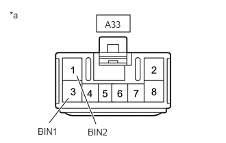
- CHECK HARNESS AND CONNECTOR (BIN1 AND BIN2 TERMINALS POWER SOURCE CIRCUIT)
*a Front view of wire harness connector
(to Engine Stop and Start ECU)- Disconnect the engine stop and start ECU connector.
- Measure the voltage according to the value(s) in the table below.
Standard Voltage
Tester Connection Condition Specified Condition A33-1 (BIN2) - Body ground Always 9.5 to 14 V A33-3 (BIN1) - Body ground Always 9.5 to 14 V Result
Proceed to OK NG
Result:
NG
REPAIR OR REPLACE HARNESS OR CONNECTOR (ENGINE STOP AND START ECU - BATTERY)
Result:
OK
See step 4
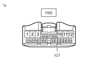
- CHECK HARNESS AND CONNECTOR (IG1 TERMINAL POWER SOURCE CIRCUIT)
*a Front view of wire harness connector
(to Engine Stop and Start ECU)- Disconnect the engine stop and start ECU connector.
- Turn the ignition switch to ON.
- Measure the voltage according to the value(s) in the table below.
Standard Voltage
Tester Connection Condition Specified Condition H66-21 (IG1) - Body ground Ignition switch ON 9.5 to 14 V Result
Proceed to OK NG
Result:
NG
REPAIR OR REPLACE HARNESS OR CONNECTOR (ENGINE STOP AND START ECU - INSTRUMENT PANEL JUNCTION BLOCK ASSEMBLY (IG1-NO. 1 RELAY))
Result:
OK
See step 5
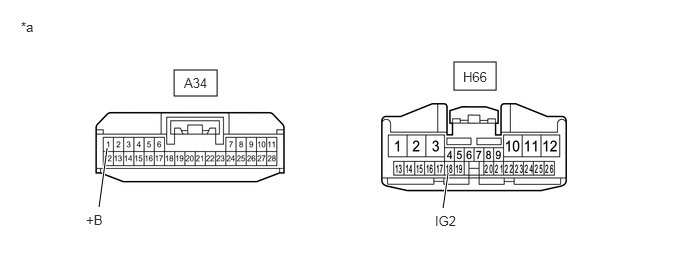
- CHECK HARNESS AND CONNECTOR (+B AND IG2 TERMINALS POWER SOURCE CIRCUIT)
*a Front view of wire harness connector
(to Engine Stop and Start ECU)- - - Disconnect the engine stop and start ECU connectors.
- Turn the ignition switch to ON.
- Measure the voltage according to the value(s) in the table below.
Standard Voltage
Tester Connection Condition Specified Condition A34-1 (+B) - Body ground Ignition switch ON 9.5 to 14 V H66-18 (IG2) - Body ground Ignition switch ON 9.5 to 14 V Result
Proceed to OK NG
Result:
NG
REPAIR OR REPLACE HARNESS OR CONNECTOR (ENGINE STOP AND START ECU - EFI-MAIN NO. 1 RELAY OR INSTRUMENT PANEL JUNCTION BLOCK ASSEMBLY (IG2-NO. 2 RELAY))
Result:
OK
See step 6
- CHECK HARNESS AND CONNECTOR (ENGINE STOP AND START ECU - BODY GROUND)
- Disconnect the engine stop and start ECU connectors.
- Measure the resistance according to the value(s) in the table below.
Standard Resistance
Tester Connection Condition Specified Condition A33-2 (GND2) - Body ground Always Below 1 Ω A33-8 (GND1) - Body ground Always Below 1 Ω A34-6 (DGND) - Body ground Always Below 1 Ω Result
Proceed to OK NG
Result:
OK
REPLACE ENGINE STOP AND START ECU. Refer to REMOVAL [12/2019 - 10/2022]
Result:
NG
REPAIR OR REPLACE HARNESS OR CONNECTOR
- PERFORM ACTIVE TEST USING GTS (STARTER (HOOD CLOSE))
- Check that the engine hood is closed.
- Check whether the engine cranks while the Active Test "Starter (Hood Close)" is being performed.
Powertrain > Stop and Start > Active Test
Tester Display Starter (Hood Close) NOTE:The Active Test "Starter (Hood Close)" is stopped automatically 3 seconds after the starter assembly begins operating.
Standard
Engine cranks
Result
Result Proceed to Engine cranks A Engine does not crank B
Result:
B
See step 13
Result:
A
See step 8
- READ VALUE USING GTS (NEUTRAL SWITCH)
- In accordance with the display on the GTS, read the Data List.
Powertrain > Stop and Start > Data List
Tester Display Neutral Switch OK
GTS Display Condition Normal Condition Neutral Switch Shift lever in P or N ON Shift lever not in P or N OFF Result
Proceed to OK NG
Result:
NG
See step 11
Result:
OK
See step 9
- In accordance with the display on the GTS, read the Data List.
- CHECK HARNESS AND CONNECTOR (CERTIFICATION ECU (SMART KEY ECU ASSEMBLY) - PARK/NEUTRAL POSITION SWITCH ASSEMBLY)
- Disconnect the certification ECU (smart key ECU assembly) connector.
- Disconnect the park/neutral position switch assembly connector.
- Disconnect the engine stop and start ECU connector.
- Disconnect the ECM connector.
- Measure the resistance according to the value(s) in the table below.
Standard Resistance
Tester Connection Condition Specified Condition A19-9 (STAR) - C52-4 (B) Always Below 1 Ω A19-9 (STAR) or C52-4 (B) - Body ground and other terminals Always 10 kΩ or higher Result
Proceed to OK NG
Result:
NG
REPAIR OR REPLACE HARNESS OR CONNECTOR
Result:
OK
See step 10
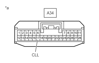
- CHECK CERTIFICATION ECU (SMART KEY ECU ASSEMBLY) (STAR SIGNAL)
- Disconnect the engine stop and start ECU connector.
*a Front view of wire harness connector
(to Engine Stop and Start ECU) - Measure the voltage according to the value(s) in the table below.
Standard Voltage
Tester Connection Condition Specified Condition A34-17 (CLL) - Body ground Engine start 9.5 to 14 V Result
Proceed to OK NG
Result:
OK
PROCEED TO NEXT SUSPECTED AREA SHOWN IN PROBLEM SYMPTOMS TABLE. Refer to PROBLEM SYMPTOMS TABLE [12/2019 - ]
Result:
NG
GO TO SMART ENTRY AND START SYSTEM. Refer to HOW TO PROCEED WITH TROUBLESHOOTING [12/2019 - 10/2021] , or refer to HOW TO PROCEED WITH TROUBLESHOOTING [10/2021 - 11/2023]
- Disconnect the engine stop and start ECU connector.
- INSPECT PARK/NEUTRAL POSITION SWITCH ASSEMBLY
- for 2WD Models:
Refer to INSPECTION [12/2019 - 10/2022]
- for AWD Models:
Refer to INSPECTION [12/2019 - 10/2022]
Result
Proceed to OK NG Result:
NG
REPLACE PARK/NEUTRAL POSITION SWITCH ASSEMBLY
- for 2WD Models:
Refer to REMOVAL [12/2019 - 10/2022]
- for AWD Models:
Refer to REMOVAL [12/2019 - 10/2022]
Result:
OK
See step 12
- for 2WD Models:
- CHECK HARNESS AND CONNECTOR (CERTIFICATION ECU (SMART KEY ECU ASSEMBLY) - ST RELAY)
- Disconnect the certification ECU (smart key ECU assembly) connector.
- Remove the ST relay from the No. 1 engine room relay block and No. 1 junction block assembly.
- Disconnect the engine stop and start ECU connector.
- Disconnect the ECM connector.
- Measure the resistance according to the value(s) in the table below.
Standard Resistance
Tester Connection Condition Specified Condition A19-9 (STAR) - 2 (ST relay) Shift lever in P or N Below 1 Ω Shift lever not in P or N 10 kΩ or higher Result
Proceed to OK NG
Result:
OK
PROCEED TO NEXT SUSPECTED AREA SHOWN IN PROBLEM SYMPTOMS TABLE. Refer to PROBLEM SYMPTOMS TABLE [12/2019 - ]
Result:
NG
REPAIR OR REPLACE HARNESS OR CONNECTOR
- INSPECT RELAY (ST RELAY)
Refer to PROCEDURE - Step 1
Result
Proceed to OK NG Result:
NG
REPLACE RELAY (ST RELAY)
Result:
OK
See step 14
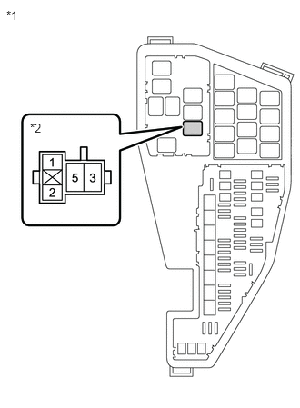
- CHECK HARNESS AND CONNECTOR (ST RELAY - BATTERY)
*1 No. 1 Engine Room Relay Block and No. 1 Junction Block Assembly *2 ST Relay - Remove the ST relay from the No. 1 engine room relay block and No. 1 junction block assembly.
- Measure the voltage according to the value(s) in the table below.
Standard Voltage
Tester Connection Condition Specified Condition 5 (ST relay) - Body ground Always 9.5 to 14 V Result
Proceed to OK NG
Result:
NG
REPAIR OR REPLACE HARNESS OR CONNECTOR (ST RELAY - BATTERY)
Result:
OK
See step 15
- CHECK HARNESS AND CONNECTOR (ST RELAY - STARTER ASSEMBLY)
- Remove the ST relay from the No. 1 engine room relay block and No. 1 junction block assembly.
- Disconnect the starter assembly connector.
- Measure the resistance according to the value(s) in the table below.
Standard Resistance
Tester Connection Condition Specified Condition 3 (ST relay) - C56-1 (ST) Always Below 1 Ω 3 (ST relay) - C58-1 (ZYV) Always Below 1 Ω Result
Proceed to OK NG
Result:
NG
REPAIR OR REPLACE HARNESS OR CONNECTOR (ST RELAY - STARTER ASSEMBLY)
Result:
OK
See step 16
- CHECK HARNESS AND CONNECTOR (ST RELAY - BODY GROUND)
- Remove the ST relay from the No. 1 engine room relay block and No. 1 junction block assembly.
- Measure the resistance according to the value(s) in the table below.
Standard Resistance
Tester Connection Condition Specified Condition 1 (ST relay) - Body ground Always Below 1 Ω Result
Proceed to OK NG
Result:
NG
REPAIR OR REPLACE HARNESS OR CONNECTOR (ST RELAY - BODY GROUND)
Result:
OK
See step 17
- CHECK HARNESS AND CONNECTOR (ENGINE STOP AND START ECU - ST RELAY)
- Disconnect the engine stop and start ECU connector.
- Remove the ST relay from the No. 1 engine room relay block and No. 1 junction block assembly.
- Disconnect the certification ECU (smart key ECU assembly) connector.
- Disconnect the park/neutral position switch assembly connector.
- Disconnect the ECM connector.
- Measure the resistance according to the value(s) in the table below.
Standard Resistance
Tester Connection Condition Specified Condition A34-21 (STA) - 2 (ST relay) Always Below 1 Ω A34-21 (STA) or 2 (ST relay) - Body ground and other terminals Always 10 kΩ or higher Result
Proceed to OK NG
Result:
NG
REPAIR OR REPLACE HARNESS OR CONNECTOR
Result:
OK
See step 18
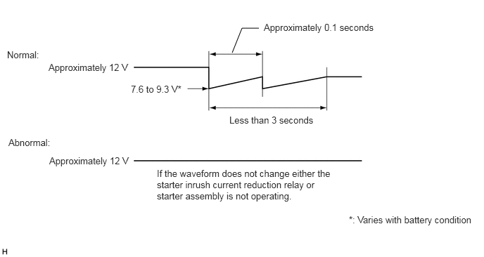
- CHECK STARTER SIGNAL (OUTPUT WAVEFORM)
- Connect the positive (+) lead of an oscilloscope to the positive (+) battery terminal and the negative (-) lead to the negative (-) battery terminal.
- While cranking the engine, count the number of times the waveform drops.
Standard
Waveform drops 2 times
Result
Number of Times Waveform Dropped Proceed to 0 times A 2 times B
Result:
B
See step 22
Result:
A
See step 19
- INSPECT STARTER INRUSH CURRENT REDUCTION RELAY
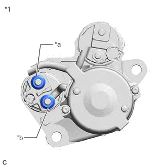
*1 Starter Assembly *a B Terminal *b M Terminal - Disconnect the cable from the negative (-) battery terminal.
- Disconnect terminals B and M of the starter inrush current reduction relay.
- Measure the resistance according to the value(s) in the table below.
Standard Resistance
Tester Connection Condition Specified Condition B Terminal - M Terminal Always Below 1 Ω Result
Proceed to OK NG
Result:
NG
See step 21
Result:
OK
See step 20
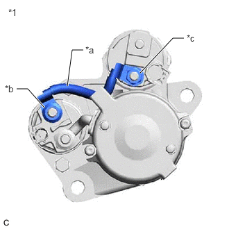
- INSPECT STARTER ASSEMBLY (WIRE HARNESS)
*1 Starter Assembly *a Inspect Part *b B Terminal *c C Terminal - Disconnect the cable from the negative (-) battery terminal.
- Disconnect terminal B of the starter inrush current reduction relay.
- Disconnect terminal C of the starter assembly.
- Measure the resistance according to the value(s) in the table below.
Standard Resistance
Tester Connection Condition Specified Condition C Terminal - B Terminal Always Below 1 Ω Result
Proceed to OK NG
Result:
OK
REPLACE STARTER ASSEMBLY. Refer to REMOVAL [12/2019 - 09/2020] , or refer to REMOVAL [09/2020 - 10/2022]
Result:
NG
REPAIR OR REPLACE WIRE HARNESS
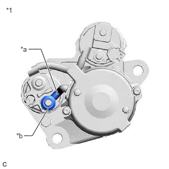
- INSPECT STARTER ASSEMBLY (M TERMINAL)
*1 Starter Assembly *a Inspect Part *b M Terminal - Disconnect the cable from the negative (-) battery terminal.
- Disconnect terminal M of the starter inrush current reduction relay.
- Measure the resistance according to the value(s) in the table below.
Standard Resistance
Tester Connection Condition Specified Condition M Terminal - Body ground Always Below 1 Ω Result
Proceed to OK NG
Result:
OK
REPLACE STARTER INRUSH CURRENT REDUCTION RELAY. Refer to PROCEDURE - Step 2
Result:
NG
REPLACE STARTER ASSEMBLY. Refer to REMOVAL [12/2019 - 09/2020] , or refer to REMOVAL [09/2020 - 10/2022]
- INSPECT STARTER ASSEMBLY
Refer to INSPECTION [12/2019 - 10/2022]
Result
Proceed to OK NG Result:
OK
PROCEED TO NEXT SUSPECTED AREA SHOWN IN PROBLEM SYMPTOMS TABLE. Refer to PROBLEM SYMPTOMS TABLE [12/2019 - ]
Result:
NG
REPLACE STARTER ASSEMBLY. Refer to REMOVAL [12/2019 - 09/2020] , or refer to REMOVAL [09/2020 - 10/2022]