DTC C14FE-14: Steering Angle Sensor Supply Voltage Circuit Short to Ground or Open [11/2023 - ]: Procedure
- CLEAR DTC
Result:
NEXT
See step 2
- RECONFIRM DTC
- Based on the Freeze Frame Data and interview with the customer, attempt to reproduce the conditions when the malfunction occurred.
- Check if the same DTC is output.
Chassis > Brake/EPB > Trouble Codes
Result
Result Proceed to DTC C14FE-14 is not output. A DTC C14FE-14 is output. B
Result:
A
USE SIMULATION METHOD TO CHECK. Refer to HOW TO PROCEED WITH TROUBLESHOOTING [12/2019 - ]
Result:
B
See step 3
- CHECK HARNESS AND CONNECTOR (IG1 TERMINAL)
- Make sure that there is no looseness at the locking part and the connecting part of the connectors.
OK
The connector is securely connected.
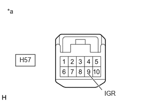
*a Front view of wire harness connector
(to Steering Angle Sensor) - Disconnect the H57 steering angle sensor connector.
- Check both the connector case and the terminals for deformation and corrosion.
OK
No deformation or corrosion.
- Turn the ignition switch to ON.
- Measure the voltage according to the value(s) in the table below.
Standard Voltage
Tester Connection Condition Specified Condition H57-9 (IGR) - Body ground Ignition switch ON 10.5 to 16 V*1
11 to 14 V*2- *1: w/ Stop and Start System
- *2: w/o Stop and Start System
Result
Result Proceed to OK A NG (w/ Stop and Start System) B NG (w/o Stop and Start System) C
Result:
B
INSPECT STOP AND START SYSTEM (BACKUP BOOST CONVERTER CIRCUIT). Refer to Backup Boost Converter Circuit [11/2023 - ]
Result:
C
REPAIR OR REPLACE HARNESS OR CONNECTOR
Result:
A
See step 4
- Make sure that there is no looseness at the locking part and the connecting part of the connectors.
- CHECK HARNESS AND CONNECTOR (BAT TERMINAL)
- Turn the ignition switch off.
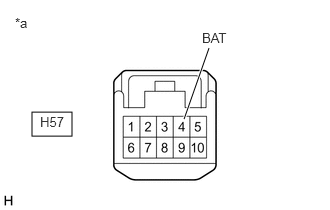
*a Front view of wire harness connector
(to Steering Angle Sensor) - Measure the voltage according to the value(s) in the table below.
Standard Voltage
Tester Connection Condition Specified Condition H57-4 (BAT) - Body ground Always 11 to 14 V Result
Proceed to OK NG
Result:
NG
REPAIR OR REPLACE HARNESS OR CONNECTOR
Result:
OK
See step 5
- Turn the ignition switch off.
- CHECK HARNESS AND CONNECTOR (ESS TERMINAL)
- Measure the resistance according to the value(s) in the table below.
Standard Resistance
Tester Connection Condition Specified Condition H57-6 (ESS) - Body ground 1 minute or more after disconnecting the cable from the negative (-) auxiliary battery terminal Below 1 Ω Result
Proceed to OK NG
Result:
OK
REPLACE STEERING ANGLE SENSOR. Refer to REMOVAL [11/2023 - ]
Result:
NG
REPAIR OR REPLACE HARNESS OR CONNECTOR
- Measure the resistance according to the value(s) in the table below.