DTC P0571-11: Brake Switch "A" Circuit Short to Ground [12/2019 - ]: Procedure
- CHECK BRAKE PEDAL HEIGHT AND STOP LIGHT SWITCH ASSEMBLY INSTALLATION
Refer to ADJUSTMENT [12/2019 - 10/2022] , or refer to ADJUSTMENT [10/2022 - ]
OK
The brake pedal height and stop light switch assembly installation are normal.
HINT:
If the on/off status of the stop light switch assembly and the pressure increase information from the master cylinder pressure sensor do not match due to an improperly installed brake pedal or stop light switch assembly, this DTC may be stored. Therefore, be sure to check the installation condition of the pedal and stop light switch assembly before inspecting the input signals and other related parts.
Result
Proceed to OK NG Result:
NG
ADJUST BRAKE PEDAL HEIGHT OR STOP LIGHT SWITCH ASSEMBLY INSTALLATION. Refer to ADJUSTMENT [12/2019 - 10/2022] , or refer to ADJUSTMENT [10/2022 - ]
Result:
OK
See step 2
- CHECK STOP LIGHT OPERATION
- Check that the stop lights come on when the brake pedal is depressed, and go off when the brake pedal is released.
OK
Condition Illumination Condition Brake pedal depressed. On Brake pedal released. Off Result
Proceed to OK NG
Result:
NG
See step 11
Result:
OK
See step 3
- Check that the stop lights come on when the brake pedal is depressed, and go off when the brake pedal is released.
- READ VALUE USING GTS (STOP LIGHT SW AND BRAKE PEDAL LOAD SENSING SWITCH)
- Check that the stop light switch display and brake pedal load sensing switch (brake pedal support assembly) display observed on the GTS change according to brake pedal operation.
Chassis > Brake/EPB > Data List
Tester Display Measurement Item Range Normal Condition Diagnostic Note Stop Light SW Stop light switch assembly status
(STP or STP2 terminal input)OFF / ON OFF: Brake pedal released
ON: Brake pedal depressedHINT: - Stop light control relay off: STP terminal status displayed.
- Stop light control relay on: STP2 terminal status displayed.
Brake Pedal Load Sensing SW Brake pedal load sensing switch (brake pedal support assembly) OFF / ON OFF: Brake pedal released
ON: Brake pedal depressed- Chassis > Brake/EPB > Data List
Tester Display Stop Light SW Brake Pedal Load Sensing SW OK
The GTS displays OFF / ON according to brake pedal operation.
- Slowly depress the brake pedal, and check when the stop light switch assembly and brake pedal load sensing switch (brake pedal support assembly) turn on.
OK
First the stop light switch assembly turns on, and then the brake pedal load sensing switch (brake pedal support assembly) turns on.
Result
Result Proceed to OK A NG (The stop light switch assembly does not turn on.) B NG (Turning on of the brake pedal load sensing switch (brake pedal support assembly) is not confirmed.) C NG (The brake pedal load sensing switch (brake pedal support assembly) turns on first.) D
Result:
B
See step 6
Result:
C
See step 10
Result:
D
REPLACE BRAKE PEDAL SUPPORT ASSEMBLY. Refer to REMOVAL [12/2019 - 10/2022] , or refer to REMOVAL [10/2022 - 11/2023] , or refer to REMOVAL [11/2023 - ]
Result:
A
See step 4
- Check that the stop light switch display and brake pedal load sensing switch (brake pedal support assembly) display observed on the GTS change according to brake pedal operation.
- CLEAR DTC
Result:
NEXT
See step 5
- RECONFIRM DTC
- Based on the Freeze Frame Data and interview with the customer, attempt to reproduce the conditions when the malfunction occurred.
- Check if the same DTC is output.
Chassis > Brake/EPB > Trouble Codes
Result
Result Proceed to DTC P0571-11 is not output. A DTC P0571-11 is output. B
Result:
A
USE SIMULATION METHOD TO CHECK. Refer to HOW TO PROCEED WITH TROUBLESHOOTING [12/2019 - ]
Result:
B
REPLACE BRAKE ACTUATOR ASSEMBLY. Refer to REMOVAL [12/2019 - 10/2022] , or refer to REMOVAL [10/2022 - 11/2023] , or refer to REMOVAL [11/2023 - ]
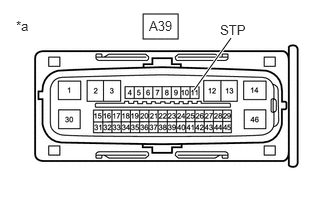
- CHECK HARNESS AND CONNECTOR (STP TERMINAL)
- Turn the ignition switch off.
*a Front view of wire harness connector
(to Skid Control ECU (Brake Actuator Assembly)) - Make sure that there is no looseness at the locking part and the connecting part of the connectors.
OK
The connector is securely connected.
- Disconnect the A39 skid control ECU (brake actuator assembly) connector.
- Check both the connector case and the terminals for deformation and corrosion.
OK
No deformation or corrosion.
- Measure the voltage according to the value(s) in the table below.
Standard Voltage
Tester Connection Condition Specified Condition A39-11 (STP) - Body ground Stop light switch assembly on (Brake pedal depressed) 8 to 14 V A39-11 (STP) - Body ground Stop light switch assembly off (Brake pedal released) Below 1.5 V Result
Proceed to OK NG
Result:
NG
REPAIR OR REPLACE HARNESS OR CONNECTOR
Result:
OK
See step 7
- Turn the ignition switch off.
- CLEAR DTC
- Reconnect the A39 skid control ECU (brake actuator assembly) connector.
- Clear the DTCs.
Chassis > Brake/EPB > Clear DTCs
- Turn the ignition switch off.
Result
Proceed to NEXT
Result:
NEXT
See step 8
- RECONFIRM DTC
- Based on the Freeze Frame Data and interview with the customer, attempt to reproduce the conditions when the malfunction occurred.
- Check if the same DTC is output.
Chassis > Brake/EPB > Trouble Codes
Result
Result Proceed to DTC P0571-11 is not output. A DTC P0571-11 is output. B
Result:
B
REPLACE BRAKE ACTUATOR ASSEMBLY. Refer to REMOVAL [12/2019 - 10/2022] , or refer to REMOVAL [10/2022 - 11/2023] , or refer to REMOVAL [11/2023 - ]
Result:
A
See step 9
- INSPECT BRAKE PEDAL SUPPORT ASSEMBLY
- Turn the ignition switch off.
- Inspect the brake pedal load sensing switch (brake pedal support assembly).
Refer to ON-VEHICLE INSPECTION [12/2019 - ]
OK
The brake pedal load sensing switch (brake pedal support assembly) is normal.
Result
Proceed to OK NG
Result:
OK
See step 10
Result:
NG
REPLACE BRAKE PEDAL SUPPORT ASSEMBLY. Refer to REMOVAL [12/2019 - 10/2022] , or refer to REMOVAL [10/2022 - 11/2023] , or refer to REMOVAL [11/2023 - ]
- CHECK HARNESS AND CONNECTOR (BRAKE PEDAL SUPPORT ASSEMBLY - BRAKE ACTUATOR ASSEMBLY)
- Make sure that there is no looseness at the locking part and the connecting part of the connectors.
OK
The connector is securely connected.
- Disconnect the A39 skid control ECU (brake actuator assembly) connector.
- Disconnect the A45 brake pedal load sensing switch (brake pedal support assembly) connector.
- Check both the connector case and the terminals for deformation and corrosion.
OK
No deformation or corrosion.
- Measure the resistance according to the value(s) in the table below.
Standard Resistance
Tester Connection Condition Specified Condition A45-2 (FSW+) - A39-28 (FSW+) Always Below 1 Ω A45-2 (FSW+) or A39-28 (FSW+) - Body ground Always 10 kΩ or higher A45-1 (FSW-) - Body ground 1 minute or more after disconnecting the cable from the negative (-) auxiliary battery terminal Below 1 Ω Result
Proceed to OK NG
Result:
OK
REPLACE BRAKE ACTUATOR ASSEMBLY. Refer to REMOVAL [12/2019 - 10/2022] , or refer to REMOVAL [10/2022 - 11/2023] , or refer to REMOVAL [11/2023 - ]
Result:
NG
REPAIR OR REPLACE HARNESS OR CONNECTOR
- Make sure that there is no looseness at the locking part and the connecting part of the connectors.
- INSPECT STOP LIGHT SWITCH ASSEMBLY
Refer to ON-VEHICLE INSPECTION [12/2019 - ]
OK
The stop light switch assembly is normal.
Result
Proceed to OK NG Result:
NG
REPLACE STOP LIGHT SWITCH ASSEMBLY. Refer to REMOVAL [12/2019 - ]
Result:
OK
See step 12
- CHECK HARNESS AND CONNECTOR (STP TERMINAL)
- Turn the ignition switch off.
*a Front view of wire harness connector
(to Skid Control ECU (Brake Actuator Assembly)) - Make sure that there is no looseness at the locking part and the connecting part of the connectors.
OK
The connector is securely connected.
- Disconnect the A39 skid control ECU (brake actuator assembly) connector.
- Check both the connector case and the terminals for deformation and corrosion.
OK
No deformation or corrosion.
- Measure the voltage according to the value(s) in the table below.
Standard Voltage
Tester Connection Condition Specified Condition A39-11 (STP) - Body ground Stop light switch assembly on (Brake pedal depressed) 8 to 14 V A39-11 (STP) - Body ground Stop light switch assembly off (Brake pedal released) Below 1.5 V Result
Proceed to OK NG
Result:
NG
REPAIR OR REPLACE HARNESS OR CONNECTOR
Result:
OK
See step 13
- Turn the ignition switch off.
- CLEAR DTC
- Reconnect the A39 skid control ECU (brake actuator assembly) connector.
- Clear the DTCs.
Chassis > Brake/EPB > Clear DTCs
- Turn the ignition switch off.
Result
Proceed to NEXT
Result:
NEXT
See step 14
- RECONFIRM DTC
- Based on the Freeze Frame Data and interview with the customer, attempt to reproduce the conditions when the malfunction occurred.
- Check if the same DTC is output.
Chassis > Brake/EPB > Trouble Codes
Result
Result Proceed to DTC P0571-11 is not output. A DTC P0571-11 is output. B
Result:
A
USE SIMULATION METHOD TO CHECK. Refer to HOW TO PROCEED WITH TROUBLESHOOTING [12/2019 - ]
Result:
B
REPLACE BRAKE ACTUATOR ASSEMBLY. Refer to REMOVAL [12/2019 - 10/2022] , or refer to REMOVAL [10/2022 - 11/2023] , or refer to REMOVAL [11/2023 - ]