DTC P0571-13: Brake Switch "A" Circuit Open [12/2019 - ]: Procedure
- CHECK STOP LIGHT OPERATION
- Check that the stop lights come on when the brake pedal is depressed.
Result
Result Proceed to All stop lights illuminate when the brake pedal is depressed and turn off when the brake pedal is released. A All stop lights do not illuminate when the brake pedal is depressed. B One or more stop lights illuminate when the brake pedal is depressed but remain on when the brake pedal is released. C
Result:
B
See step 10
Result:
C
See step 6
Result:
A
See step 2
- Check that the stop lights come on when the brake pedal is depressed.
- READ VALUE USING GTS (STOP LIGHT SWITCH ASSEMBLY)
- Check the value of Stop Light SW when the brake pedal is depressed.
Chassis > Brake/EPB > Data List
Tester Display Measurement Item Range Normal Condition Diagnostic Note Stop Light SW Stop light switch assembly status
(STP or STP2 terminal input)OFF / ON OFF: Brake pedal released
ON: Brake pedal depressedHINT: - Stop light control relay off: STP terminal status displayed.
- Stop light control relay on: STP2 terminal status displayed.
Chassis > Brake/EPB > Data List
Tester Display Stop Light SW Result
Result Proceed to The value of Stop Light SW is ON. A Other than above. B
Result:
B
See step 9
Result:
A
See step 3
- Check the value of Stop Light SW when the brake pedal is depressed.
- STOP LIGHT SWITCH ASSEMBLY OUTPUT CIRCUIT INSPECTION
- Turn the ignition switch off.
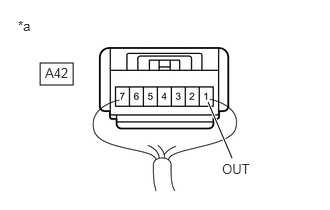
*a Component with harness connected
(Stop Light Switch Assembly) - Make sure that there is no looseness at the locking part and the connecting part of the connector.
OK
The connector is securely connected.
- Turn the ignition switch to ON.
- Measure the voltage according to the value(s) in the table below.
Standard Voltage
Tester Connection Condition Specified Condition A42-1 (OUT) - Body ground - Ignition switch ON
- The headlights are on
- The blower motor switch is in the HI position
- The rear window defogger is turned on
- Stop light switch assembly off (Brake pedal released)
Below 1.5 V Result
Proceed to OK NG
Result:
NG
See step 6
Result:
OK
See step 4
- Turn the ignition switch off.
- CLEAR DTC
Result:
NEXT
See step 5
- RECONFIRM DTC
- Based on the Freeze Frame Data and interview with the customer, attempt to reproduce the conditions when the malfunction occurred.
- Check if the same DTC is output.
Chassis > Brake/EPB > Trouble Codes
Result
Result Proceed to DTC P0571-13 is not output. A DTC P0571-13 is output. B
Result:
A
USE SIMULATION METHOD TO CHECK. Refer to HOW TO PROCEED WITH TROUBLESHOOTING [12/2019 - ]
Result:
B
REPLACE BRAKE ACTUATOR ASSEMBLY. Refer to REMOVAL [12/2019 - 10/2022] , or refer to REMOVAL [10/2022 - 11/2023] , or refer to REMOVAL [11/2023 - ]
- CHECK STOP LIGHT SWITCH ASSEMBLY
- Turn the ignition switch off.
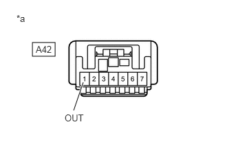
*a Front view of wire harness connector
(to Stop Light Switch Assembly) - Make sure that there is no looseness at the locking part and the connecting part of the connector.
OK
The connector is securely connected.
- Disconnect the A42 stop light switch assembly connector.
- Check both the connector case and the terminals for deformation and corrosion.
OK
No deformation or corrosion.
- Measure the voltage according to the value(s) in the table below.
Standard Voltage
Tester Connection Condition Specified Condition A42-1 (OUT) - Body ground Stop light switch assembly off
(Brake pedal released)Below 1.5 V Result
Proceed to OK NG
Result:
OK
REPLACE STOP LIGHT SWITCH ASSEMBLY. Refer to REMOVAL [12/2019 - ]
Result:
NG
See step 7
- Turn the ignition switch off.
- CHECK BRAKE ACTUATOR ASSEMBLY
- Make sure that there is no looseness at the locking part and the connecting part of the connector.
*a Front view of wire harness connector
(to Stop Light Switch Assembly)OK
The connector is securely connected.
- Disconnect the A39 skid control ECU (brake actuator assembly) connector.
- Check both the connector case and the terminals for deformation and corrosion.
OK
No deformation or corrosion.
- Measure the voltage according to the value(s) in the table below.
Standard Voltage
Tester Connection Condition Specified Condition A42-1 (OUT) - Body ground Stop light switch assembly off
(Brake pedal released)Below 1.5 V Result
Proceed to OK NG
Result:
OK
REPLACE BRAKE ACTUATOR ASSEMBLY. Refer to REMOVAL [12/2019 - 10/2022] , or refer to REMOVAL [10/2022 - 11/2023] , or refer to REMOVAL [11/2023 - ]
Result:
NG
See step 8
- Make sure that there is no looseness at the locking part and the connecting part of the connector.
- CHECK FOR SHORT TO +B IN STP CIRCUIT
- Check that there is no short to +B in the STP circuit (wire harnesses, connectors and stop lights).
OK
No short to +B.
Result
Proceed to OK NG
Result:
OK
USE SIMULATION METHOD TO CHECK. Refer to HOW TO PROCEED WITH TROUBLESHOOTING [12/2019 - ]
Result:
NG
REPAIR OR REPLACE MALFUNCTIONING PART
- Check that there is no short to +B in the STP circuit (wire harnesses, connectors and stop lights).
- CHECK HARNESS AND CONNECTOR (STP TERMINAL)
- Turn the ignition switch off.
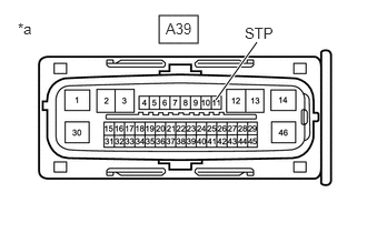
*a Front view of wire harness connector
(to Skid Control ECU (Brake Actuator Assembly)) - Make sure that there is no looseness at the locking part and the connecting part of the connector.
OK
The connector is securely connected.
- Disconnect the A39 skid control ECU (brake actuator assembly) connector.
- Check both the connector case and the terminals for deformation and corrosion.
OK
No deformation or corrosion.
- Measure the voltage according to the value(s) in the table below.
Standard Voltage
Tester Connection Condition Specified Condition A39-11 (STP) - Body ground Stop light switch assembly on
(Brake pedal depressed)11 to 14 V Result
Proceed to OK NG
Result:
OK
REPLACE BRAKE ACTUATOR ASSEMBLY. Refer to REMOVAL [12/2019 - 10/2022] , or refer to REMOVAL [10/2022 - 11/2023] , or refer to REMOVAL [11/2023 - ]
Result:
NG
REPAIR OR REPLACE HARNESS OR CONNECTOR
- Turn the ignition switch off.
- CHECK HARNESS AND CONNECTOR (STOP LIGHT SWITCH ASSEMBLY - STOP LIGHT)
- Check that there is no open in the wire harnesses and connectors from terminal OUT of the stop light switch assembly to the stop lights.
OK
No open.
Result
Proceed to OK NG
Result:
OK
REPLACE BRAKE ACTUATOR ASSEMBLY. Refer to REMOVAL [12/2019 - 10/2022] , or refer to REMOVAL [10/2022 - 11/2023] , or refer to REMOVAL [11/2023 - ]
Result:
NG
REPAIR OR REPLACE HARNESS OR CONNECTOR
- Check that there is no open in the wire harnesses and connectors from terminal OUT of the stop light switch assembly to the stop lights.