DTC C0540-17: Brake Pressure Sensor "A" Circuit Voltage Above Threshold [12/2019 - ]: Procedure
- CLEAR DTC
Result:
NEXT
See step 2
- RECONFIRM DTC
- Based on the Freeze Frame Data and interview with the customer, attempt to reproduce the conditions when the malfunction occurred.
- Check if the same DTC is output.
Chassis > Brake/EPB > Trouble Codes
Result
Result Proceed to DTC C0540-17 is output A DTCs C0540-17 and P0571-13 are output B
Result:
B
GO TO DTC CHART (P0571-13). Refer to DTC P0571-13: Brake Switch "A" Circuit Open [12/2019 - ]
Result:
A
See step 3
- READ VALUE USING GTS (STOP LIGHT SWITCH ASSEMBLY)
- Check that the stop light switch assembly condition observed on the GTS changes according to brake pedal operation.
Chassis > Brake/EPB > Data List
Tester Display Measurement Item Range Normal Condition Diagnostic Note Stop Light SW Stop light switch assembly status
(STP or STP2 terminal input)OFF / ON OFF: Brake pedal released
ON: Brake pedal depressedHINT: - Stop light control relay off: STP terminal status displayed.
- Stop light control relay on: STP2 terminal status displayed.
Chassis > Brake/EPB > Data List
Tester Display Stop Light SW OK
The GTS displays OFF / ON according to brake pedal operation.
Result
Proceed to OK NG
Result:
NG
See step 7
Result:
OK
See step 4
- Check that the stop light switch assembly condition observed on the GTS changes according to brake pedal operation.
- READ VALUE USING GTS (MASTER CYLINDER SENSOR)
- Start the engine.
- Check the value of Data List item Master Cylinder Sensor 1 when the brake pedal is released.
Chassis > Brake/EPB > Data List
Tester Display Measurement Item Range Normal Condition Diagnostic Note Master Cylinder Sensor 1 Master cylinder pressure sensor pressure (value detected by ECU) Min.: -1.00 MPa
Max.: 23.99 MPaBrake pedal released: -1.00 to 0.00 MPa Reading increases when brake pedal is depressed Chassis > Brake/EPB > Data List
Tester Display Master Cylinder Sensor 1 OK
The value of Data List item Master Cylinder 1 is within standard range.
Result
Proceed to OK NG
Result:
NG
REPLACE BRAKE ACTUATOR ASSEMBLY. Refer to REMOVAL [12/2019 - 10/2022] , or refer to REMOVAL [10/2022 - 11/2023] , or refer to REMOVAL [11/2023 - ]
Result:
OK
See step 5
- CLEAR DTC
Result:
NEXT
See step 6
- RECONFIRM DTC
- Based on the Freeze Frame Data and interview with the customer, attempt to reproduce the conditions when the malfunction occurred.
- Check if the same DTC is output.
Chassis > Brake/EPB > Trouble Codes
Result
Result Proceed to DTC C0540-17 is not output. A DTC C0540-17 is output. B
Result:
A
USE SIMULATION METHOD TO CHECK. Refer to HOW TO PROCEED WITH TROUBLESHOOTING [12/2019 - ]
Result:
B
REPLACE BRAKE ACTUATOR ASSEMBLY. Refer to REMOVAL [12/2019 - 10/2022] , or refer to REMOVAL [10/2022 - 11/2023] , or refer to REMOVAL [11/2023 - ]
- CHECK STOP LIGHT SWITCH ASSEMBLY INSTALLATION
- Turn the ignition switch off.
- Check the stop light switch assembly installation.
Refer to INSTALLATION [12/2019 - ]
OK
The stop light switch assembly installation are normal.
Result
Proceed to OK NG
Result:
NG
INSTALL STOP LIGHT SWITCH ASSEMBLY CORRECTLY. Refer to INSTALLATION [12/2019 - ]
Result:
OK
See step 8
- INSPECT STOP LIGHT SWITCH ASSEMBLY
Refer to ON-VEHICLE INSPECTION [12/2019 - ]
OK
The stop light switch assembly is normal.
Result
Proceed to OK NG Result:
NG
REPLACE STOP LIGHT SWITCH ASSEMBLY. Refer to REMOVAL [12/2019 - ]
Result:
OK
See step 9
- CHECK HARNESS AND CONNECTOR (STP TERMINAL)
- Make sure that there is no looseness at the locking part and the connecting part of the connectors.
OK
The connector is securely connected.
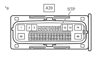
*a Front view of wire harness connector
(to Skid Control ECU (Brake Actuator Assembly)) - Disconnect the A39 skid control ECU (brake actuator assembly) connector.
- Check both the connector case and the terminals for deformation and corrosion.
OK
No deformation or corrosion.
- Measure the voltage according to the value(s) in the table below.
Standard Voltage
Tester Connection Condition Specified Condition A39-11 (STP) - Body ground Stop light switch assembly on (Brake pedal depressed) 8 to 14 V A39-11 (STP) - Body ground Stop light switch assembly off (Brake pedal released) Below 1.5 V Result
Proceed to OK NG
Result:
OK
REPLACE BRAKE ACTUATOR ASSEMBLY. Refer to REMOVAL [12/2019 - 10/2022] , or refer to REMOVAL [10/2022 - 11/2023] , or refer to REMOVAL [11/2023 - ]
Result:
NG
REPAIR OR REPLACE HARNESS OR CONNECTOR
- Make sure that there is no looseness at the locking part and the connecting part of the connectors.