DTC B2355-87: Power Distribution Box Missing Message; DTC B2357-87: Wiper Module Missing Message [11/2023 - ]: Procedure
- CLEAR DTC
Result:
NEXT
See step 2
- CHECK FOR DTC
- Check for DTCs.
Body Electrical > Main Body > Trouble Codes
Result
Result Proceed to B2355-87 and B2357-87 are output A DTC B2355-87 is output B DTC B2357-87 is output C DTC is not output D
Result:
B
See step 9
Result:
C
See step 10
Result:
D
USE SIMULATION METHOD TO CHECK. Refer to HOW TO PROCEED WITH TROUBLESHOOTING [12/2019 - ]
Result:
A
See step 3
- Check for DTCs.
- CLEAR DTC
- Disconnect the A7 windshield wiper relay assembly connector.
- Clear the DTCs.
Body Electrical > Main Body > Clear DTCs
Result
Proceed to NEXT
Result:
NEXT
See step 4
- CHECK WINDSHIELD WIPER RELAY ASSEMBLY
- Check for DTCs.
Body Electrical > Main Body > Trouble Codes
Result
Result Proceed to B2355-87 and B2357-87 are output A Only B2357-87 is output B
Result:
B
REPLACE WINDSHIELD WIPER RELAY ASSEMBLY. Refer to REMOVAL [11/2023 - ]
Result:
A
See step 5
- Check for DTCs.
- CHECK HARNESS AND CONNECTOR (POWER DISTRIBUTION BOX ASSEMBLY - EACH ECU)
- Disconnect the cable from the negative (-) auxiliary battery terminal.
- Disconnect the 8E power distribution box assembly connector.
- Disconnect the A7 windshield wiper relay assembly connector.
- Measure the resistance according to the value(s) in the table below.
Standard Resistance
Tester Connection Condition Specified Condition 8E-5 - Body ground Cable disconnected from negative (-) auxiliary battery terminal 10 kΩ or higher Result
Proceed to OK NG
Result:
NG
REPAIR OR REPLACE HARNESS OR CONNECTOR
Result:
OK
See step 6
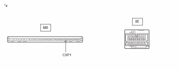
- INSPECT POWER DISTRIBUTION BOX ASSEMBLY
- Remove the power distribution box assembly.
Refer to REMOVAL [11/2023 - ]
- Remove the main body ECU (multiplex network body ECU) from the power distribution box assembly.
- Measure the resistance according to the value(s) in the table below.
*a Component without harness connected
(Power Distribution Box Assembly)- - STANDARD RESISTANCETester Connection Condition Specified Condition MB-22 (CXP1) - 8E-5 Always Below 1 Ω Result
Proceed to OK NG
Result:
NG
REPLACE POWER DISTRIBUTION BOX ASSEMBLY. Refer to REMOVAL [11/2023 - ]
Result:
OK
See step 7
- Remove the power distribution box assembly.
- CLEAR DTC
- Replace the power distribution box assembly with a new or known good one.
Refer to REMOVAL [11/2023 - ]
- Reconnect the all connectors.
- Clear the DTCs.
Body Electrical > Main Body > Clear DTCs
Result
Proceed to NEXT
Result:
NEXT
See step 8
- Replace the power distribution box assembly with a new or known good one.
- CHECK POWER DISTRIBUTION BOX ASSEMBLY
- Check for DTCs.
Body Electrical > Main Body > Trouble Codes
Result
Result Proceed to B2355-87 and B2357-87 are output A DTCs are not output B
Result:
A
REPLACE MAIN BODY ECU (MULTIPLEX NETWORK BODY ECU). Refer to REMOVAL [11/2023 - ]
Result:
B
END (POWER DISTRIBUTION BOX ASSEMBLY WAS DEFECTIVE)
- Check for DTCs.
- CHECK HARNESS AND CONNECTOR (POWER DISTRIBUTION BOX ASSEMBLY - POWER SOURCE AND BODY GROUND)
- Disconnect the 8B, 8C or 8J power distribution box assembly connector.
- Measure the voltage according to the value(s) in the table below.
Standard Voltage
Tester Connection Condition Specified Condition 8J-1 - Body ground Always 11 to 14 V - Measure the resistance according to the value(s) in the table below.
Standard Resistance
Tester Connection Condition Specified Condition 8C-41 - Body ground Always Below 1 Ω 8B-36 - Body ground Always Below 1 Ω Result
Proceed to OK NG
Result:
OK
REPLACE POWER DISTRIBUTION BOX ASSEMBLY. Refer to REMOVAL [11/2023 - ]
Result:
NG
REPAIR OR REPLACE HARNESS OR CONNECTOR
- CHECK HARNESS AND CONNECTOR (WINDSHIELD WIPER RELAY ASSEMBLY - POWER SOURCE AND BODY GROUND)
- Disconnect the A6 windshield wiper relay assembly connector.
- Measure the voltage according to the value(s) in the table below.
Standard Voltage
Tester Connection Condition Specified Condition A6-6 (IGWS) - Body ground Ignition switch ON 11 to 14 V A6-8 (+B) - Body ground Ignition switch ON or less than approximately 60 seconds after ignition switch turned off 11 to 14 V Approximately 60 seconds or more after ignition switch turned off - Measure the resistance according to the value(s) in the table below.
Standard Resistance
Tester Connection Condition Specified Condition A6-3 (E) - Body ground Always Below 1 Ω Result
Proceed to OK NG
Result:
NG
REPAIR OR REPLACE HARNESS OR CONNECTOR
Result:
OK
See step 11
- CHECK HARNESS AND CONNECTOR (WINDSHIELD WIPER RELAY ASSEMBLY - POWER DISTRIBUTION BOX ASSEMBLY)
- Turn the ignition switch off.
- Disconnect the cable from the negative (-) auxiliary battery terminal.
- Disconnect the A7 windshield wiper relay assembly connector.
- Disconnect the 8E power distribution box assembly connector.
- Measure the resistance according to the value(s) in the table below.
Standard Resistance
Tester Connection Condition Specified Condition A7-4 (MPX1) - 8E-5 Cable disconnected from negative (-) auxiliary battery terminal Below 1 Ω A7-4 (MPX1) or 8E-5 - Body ground Cable disconnected from negative (-) auxiliary battery terminal 10 kΩ or higher Result
Proceed to OK NG
Result:
OK
REPLACE WINDSHIELD WIPER RELAY ASSEMBLY. Refer to REMOVAL [11/2023 - ]
Result:
NG
REPAIR OR REPLACE HARNESS OR CONNECTOR