DTC C050C-12: Left Rear Wheel Speed Sensor Circuit Short to Battery [11/2023 - ]: Procedure
- CHECK VEHICLE SPECIFICATION
Result:
B
See step 6
Result:
A
See step 2
- CHECK HARNESS AND CONNECTOR (SENSOR GROUND CIRCUIT)
- Make sure that there is no looseness at the locking part and the connecting part of the connectors.
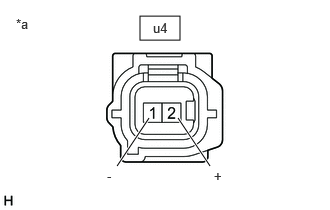
*a Front view of skid control sensor wire LH (No. 2 parking brake wire assembly)
(to Rear Speed Sensor LH (Rear Axle Hub and Bearing Assembly LH))OK
The connector is securely connected.
- Disconnect the u4 rear speed sensor LH (rear axle hub and bearing assembly LH) connector.
- Check both the connector case and the terminals for deformation and corrosion.
OK
No deformation or corrosion.
- Turn the ignition switch to ON.
- Measure the voltage according to the value(s) in the table below.
Standard Voltage
Tester Connection Condition Specified Condition u4-2 (+) - u4-1 (-) Ignition switch ON 11 to 14 V HINT:
- The rear speed sensor LH is incorporated into the rear axle hub and bearing assembly LH.
- If the rear speed sensor LH needs to be replaced, replace the rear axle hub and bearing assembly LH.
Result
Proceed to OK NG
Result:
OK
REPLACE REAR AXLE HUB AND BEARING ASSEMBLY LH. Refer to REMOVAL [11/2023 - ]
Result:
NG
See step 3
- Make sure that there is no looseness at the locking part and the connecting part of the connectors.
- CHECK HARNESS AND CONNECTOR (SENSOR GROUND CIRCUIT)
- Turn the ignition switch off.
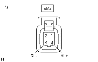
*a Front view of wire harness connector
(to Skid Control Sensor Wire LH (No. 2 Parking Brake Wire Assembly)) - Make sure that there is no looseness at the locking part and the connecting part of the connectors.
OK
The connector is securely connected.
- Disconnect the uM2 skid control sensor wire LH (No. 2 parking brake wire assembly) connector.
- Check both the connector case and the terminals for deformation and corrosion.
OK
No deformation or corrosion.
- Turn the ignition switch to ON.
- Measure the voltage according to the value(s) in the table below.
Standard Voltage
Tester Connection Condition Specified Condition uM2-3 (RL+) - uM2-4 (RL-) Ignition switch ON 11 to 14 V Result
Proceed to OK NG
Result:
OK
REPLACE NO. 2 PARKING BRAKE WIRE ASSEMBLY
Result:
NG
See step 4
- Turn the ignition switch off.
- CHECK HARNESS AND CONNECTOR (SENSOR GROUND CIRCUIT)
- Turn the ignition switch off.
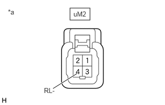
*a Front view of wire harness connector
(to Skid Control Sensor Wire LH (No. 2 Parking Brake Wire Assembly)) - Make sure that there is no looseness at the locking part and the connecting part of the connectors.
OK
The connector is securely connected.
- Disconnect the A39 skid control ECU (brake actuator assembly) connector.
- Check both the connector case and the terminals for deformation and corrosion.
OK
No deformation or corrosion.
- Measure the voltage according to the value(s) in the table below.
Standard Voltage
Tester Connection Condition Specified Condition uM2-4 (RL-) - Body ground Always Below 1.5 V Result
Proceed to OK NG
Result:
NG
REPAIR OR REPLACE HARNESS OR CONNECTOR
Result:
OK
See step 5
- Turn the ignition switch off.
- CHECK HARNESS AND CONNECTOR (NO. 2 PARKING BRAKE WIRE ASSEMBLY - BRAKE ACTUATOR ASSEMBLY)
- Measure the resistance according to the value(s) in the table below.
Standard Resistance
Tester Connection Condition Specified Condition uM2-3 (RL+) or A39-5 (RL+) - uM2-4 (RL-) or A39-4 (RL-) Always 10 kΩ or higher Result
Proceed to OK NG
Result:
OK
REPLACE BRAKE ACTUATOR ASSEMBLY. Refer to REMOVAL [11/2023 - ]
Result:
NG
REPAIR OR REPLACE HARNESS OR CONNECTOR
- Measure the resistance according to the value(s) in the table below.
- CHECK HARNESS AND CONNECTOR (SENSOR GROUND CIRCUIT)
- Make sure that there is no looseness at the locking part and the connecting part of the connectors.
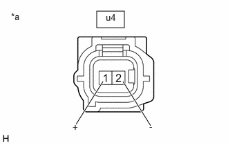
*a Front view of skid control sensor wire LH (No. 2 parking brake wire assembly)
(to Rear Skid Control Sensor LH)OK
The connector is securely connected.
- Disconnect the u4 rear skid control sensor LH connector.
- Check both the connector case and the terminals for deformation and corrosion.
OK
No deformation or corrosion.
- Turn the ignition switch to ON.
- Measure the voltage according to the value(s) in the table below.
Standard Voltage
Tester Connection Condition Specified Condition u4-1 (+) - u4-2 (-) Ignition switch ON 11 to 14 V Result
Proceed to OK NG
Result:
OK
REPLACE REAR SKID CONTROL SENSOR LH. Refer to REMOVAL [12/2019 - ]
Result:
NG
See step 7
- Make sure that there is no looseness at the locking part and the connecting part of the connectors.
- CHECK HARNESS AND CONNECTOR (SENSOR GROUND CIRCUIT)
- Turn the ignition switch off.
*a Front view of wire harness connector
(to Skid Control Sensor Wire LH (No. 2 Parking Brake Wire Assembly)) - Make sure that there is no looseness at the locking part and the connecting part of the connectors.
OK
The connector is securely connected.
- Disconnect the uM2 skid control sensor wire LH (No. 2 parking brake wire assembly) connector.
- Check both the connector case and the terminals for deformation and corrosion.
OK
No deformation or corrosion.
- Turn the ignition switch to ON.
- Measure the voltage according to the value(s) in the table below.
Standard Voltage
Tester Connection Condition Specified Condition uM2-3 (RL+) - uM2-4 (RL-) Ignition switch ON 11 to 14 V Result
Proceed to OK NG
Result:
OK
REPLACE NO. 2 PARKING BRAKE WIRE ASSEMBLY
Result:
NG
See step 8
- Turn the ignition switch off.
- CHECK HARNESS AND CONNECTOR (SENSOR GROUND CIRCUIT)
- Turn the ignition switch off.
*a Front view of wire harness connector
(to Skid Control Sensor Wire LH (No. 2 Parking Brake Wire Assembly)) - Make sure that there is no looseness at the locking part and the connecting part of the connectors.
OK
The connector is securely connected.
- Disconnect the A39 skid control ECU (brake actuator assembly) connector.
- Check both the connector case and the terminals for deformation and corrosion.
OK
No deformation or corrosion.
- Measure the voltage according to the value(s) in the table below.
Standard Voltage
Tester Connection Condition Specified Condition uM2-4 (RL-) - Body ground Always Below 1.5 V Result
Proceed to OK NG
Result:
NG
REPAIR OR REPLACE HARNESS OR CONNECTOR
Result:
OK
See step 9
- Turn the ignition switch off.
- CHECK HARNESS AND CONNECTOR (NO. 2 PARKING BRAKE WIRE ASSEMBLY - BRAKE ACTUATOR ASSEMBLY)
- Measure the resistance according to the value(s) in the table below.
Standard Resistance
Tester Connection Condition Specified Condition uM2-3 (RL+) or A39-5 (RL+) - uM2-4 (RL-) or A39-4 (RL-) Always 10 kΩ or higher Result
Proceed to OK NG
Result:
OK
REPLACE BRAKE ACTUATOR ASSEMBLY. Refer to REMOVAL [11/2023 - ]
Result:
NG
REPAIR OR REPLACE HARNESS OR CONNECTOR
- Measure the resistance according to the value(s) in the table below.