Terminals Of Ecu [11/2023 - ]
NOTE:
- Do not remove or install the power distribution box assembly with the negative (-) auxiliary battery terminal connected.
- After turning the ignition switch off, waiting time may be required before disconnecting the cable from the negative (-) auxiliary battery terminal. Therefore, make sure to read the disconnecting the cable from the negative (-) auxiliary battery terminal notices before proceeding with work.
Refer to PRECAUTION [11/2023 - ]
- When disconnecting the cable from the negative (-) auxiliary battery terminal while performing repairs, some systems need to be initialized after the cable is reconnected.
Refer to WORK PROCEDURE [11/2023 - ]
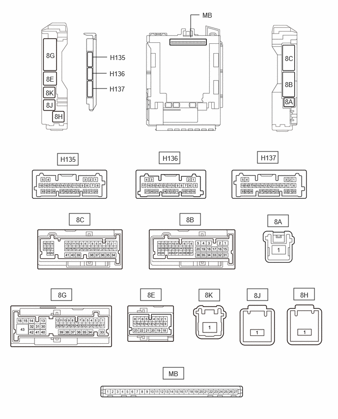
- CHECK POWER DISTRIBUTION BOX ASSEMBLY AND MAIN BODY ECU (MULTIPLEX NETWORK BODY ECU)
- Remove the main body ECU (multiplex network body ECU).
Refer to TERMINALS OF ECU [11/2023 - ]
- Reconnect the power distribution box assembly connectors.
- Measure the voltage and resistance according to the value(s) in the table below.
Terminal No. (Symbol) Terminal Description Condition Specified Condition MB-13 (GND1) - Body ground Ground Always Below 1 Ω MB-14 (GND2) - Body ground Ground Always Below 1 Ω MB-26 (BECU) - Body ground Auxiliary battery power supply Always 11 to 14 V MB-27 (IGR) - Body ground IG power supply Ignition switch off Below 1 V Ignition switch ON 11 to 14 V - Install the main body ECU (multiplex network body ECU).
Refer to INSTALLATION [11/2023 - ]
- Measure the voltage and check for pulses according to the value(s) in the table below.
Terminal No. (Symbol) Terminal Description Condition Specified Condition 8E-5 - Body ground CXPI communication line Ignition switch ON Pulse generation
- Remove the main body ECU (multiplex network body ECU).
- CHECK WINDSHIELD WIPER RELAY ASSEMBLY
Refer to REMOVAL [11/2023 - ]