ECM Power Source Circuit [11/2023 - ]: Procedure
- CHECK HARNESS AND CONNECTOR (ECM - BODY GROUND)
- Disconnect the ECM connector.
- Measure the resistance according to the value(s) in the table below.
Standard Resistance
Tester Connection Condition Specified Condition A27-10 (E1) - Body ground Always Below 1 Ω Result
Proceed to OK NG
Result:
NG
REPAIR OR REPLACE HARNESS OR CONNECTOR
Result:
OK
See step 2
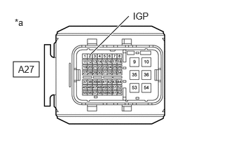
- CHECK TERMINAL VOLTAGE (IGP TERMINAL VOLTAGE)
*a Front view of wire harness connector
(to ECM)- Disconnect the ECM connector.
- Turn the ignition switch to ON.
- Measure the voltage according to the value(s) in the table below.
Standard Voltage
Tester Connection Condition Specified Condition A27-2 (IGP) - Body ground Ignition switch ON 11 to 14 V Result
Proceed to OK NG
Result:
NG
See step 6
Result:
OK
See step 3
- INSPECT EFI-MAIN NO. 1 RELAY
Refer to PROCEDURE - Step 1
Result
Proceed to OK NG Result:
NG
REPLACE EFI-MAIN NO. 1 RELAY
Result:
OK
See step 4
- CHECK HARNESS AND CONNECTOR (EFI-MAIN NO. 1 RELAY - ECM)
- Remove the EFI-MAIN NO. 1 relay from the No. 1 engine room relay block and No. 1 junction block assembly.
- Remove the VVT, EFI-MAIN NO. 2 and EFI-MAIN NO. 3 relays from the No. 1 engine room relay block and No. 1 junction block assembly.
HINT:
Remove the VVT, EFI-MAIN NO. 2 and EFI-MAIN NO. 3 relays connected between the checked terminals as the coil inside the relay influences the measurement value.
- Disconnect the ECM connector.
- Measure the resistance according to the value(s) in the table below.
Standard Resistance
Tester Connection Condition Specified Condition 2 (EFI-MAIN NO. 1 relay) - A27-15 (MREL) Always Below 1 Ω 5 (EFI-MAIN NO. 1 relay) - A27-9 (+B) Always Below 1 Ω 5 (EFI-MAIN NO. 1 relay) - A27-35 (+B2) Always Below 1 Ω 2 (EFI-MAIN NO. 1 relay) or A27-15 (MREL) - Body ground and other terminals Always 10 kΩ or higher 5 (EFI-MAIN NO. 1 relay), A27-9 (+B) or A27-35 (+B2) - Body ground and other terminals Always 10 kΩ or higher Result
Proceed to OK NG
Result:
NG
REPAIR OR REPLACE HARNESS OR CONNECTOR
Result:
OK
See step 5
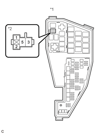
- CHECK TERMINAL VOLTAGE (POWER SOURCE OF EFI-MAIN NO. 1 RELAY)
*1 No. 1 Engine Room Relay Block and No. 1 Junction Block Assembly *2 EFI-MAIN NO. 1 Relay - Remove the EFI-MAIN NO. 1 relay from the No. 1 engine room relay block and No. 1 junction block assembly.
- Measure the voltage according to the value(s) in the table below.
Standard Voltage
Tester Connection Condition Specified Condition 3 (EFI-MAIN NO. 1 relay) - Body ground Always 11 to 14 V 1 (EFI-MAIN NO. 1 relay) - Body ground Always 11 to 14 V Result
Proceed to OK NG
Result:
OK
PROCEED TO NEXT SUSPECTED AREA SHOWN IN PROBLEM SYMPTOMS TABLE. Refer to PROBLEM SYMPTOMS TABLE [11/2023 - ]
Result:
NG
REPAIR OR REPLACE HARNESS OR CONNECTOR (AUXILIARY BATTERY - EFI-MAIN NO. 1 RELAY)
- INSPECT IGP NO. 1 RELAY
Refer to PROCEDURE - Step 6
Result
Proceed to OK NG Result:
NG
REPLACE IGP NO. 1 RELAY
Result:
OK
See step 7
- CHECK HARNESS AND CONNECTOR (IGP NO. 1 RELAY - ECM)
- Remove the IGP NO. 1 relay from the No. 1 engine room relay block and No. 1 junction block assembly.
- Disconnect the ECM connector.
- Measure the resistance according to the value(s) in the table below.
Standard Resistance
Tester Connection Condition Specified Condition 5 (IGP NO. 1 relay) - A27-2 (IGP) Always Below 1 Ω 5 (IGP NO. 1 relay) or A27-2 (IGP) - Body ground and other terminals Always 10 kΩ or higher Result
Proceed to OK NG
Result:
NG
REPAIR OR REPLACE HARNESS OR CONNECTOR
Result:
OK
See step 8
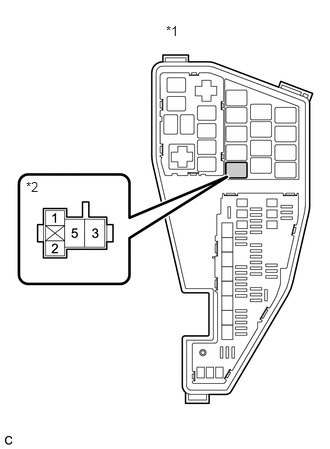
- CHECK TERMINAL VOLTAGE (POWER SOURCE OF IGP NO. 1 RELAY)
*1 No. 1 Engine Room Relay Block and No. 1 Junction Block Assembly *2 IGP NO. 1 Relay - Remove the IGP NO. 1 relay from the No. 1 engine room relay block and No. 1 junction block assembly.
- Measure the voltage according to the value(s) in the table below.
Standard Voltage
Tester Connection Condition Specified Condition 3 (IGP NO. 1 relay) - Body ground Always 11 to 14 V Result
Proceed to OK NG
Result:
NG
REPAIR OR REPLACE HARNESS OR CONNECTOR (AUXILIARY BATTERY - IGP NO. 1 RELAY)
Result:
OK
See step 9
- CHECK HARNESS AND CONNECTOR (IGP NO. 1 RELAY - BODY GROUND)
- Remove the IGP NO. 1 relay from the No. 1 engine room relay block and No. 1 junction block assembly.
- Measure the resistance according to the value(s) in the table below.
Standard Resistance
Tester Connection Condition Specified Condition 2 (IGP NO. 1 relay) - Body ground Always Below 1 Ω Result
Proceed to OK NG
Result:
NG
REPAIR OR REPLACE HARNESS OR CONNECTOR
Result:
OK
See step 10
- CHECK HARNESS AND CONNECTOR (CERTIFICATION ECU (SMART KEY ECU ASSEMBLY) - IGP NO. 1 RELAY)
- Disconnect the certification ECU (smart key ECU assembly) connector.
- Remove the IGP NO. 1 relay from the No. 1 engine room relay block and No. 1 junction block assembly.
- Measure the resistance according to the value(s) in the table below.
Standard Resistance
Tester Connection Condition Specified Condition A88-24 (IGPD) - 1 (IGP NO. 1 relay) Always Below 1 Ω A88-24 (IGPD) or 1 (IGP NO. 1 relay) - Body ground and other terminals Always 10 kΩ or higher Result
Proceed to OK NG
Result:
OK
GO TO SMART KEY SYSTEM. Refer to HOW TO PROCEED WITH TROUBLESHOOTING [11/2023 - ]
Result:
NG
REPAIR OR REPLACE HARNESS OR CONNECTOR