DTC B2325: LIN Communication Bus Malfunction [12/2019 - 11/2023]: Procedure
- CHECK POWER WINDOW REGULATOR MOTOR ASSEMBLY (DRIVER DOOR)
- Disconnect the J24 power window regulator motor assembly (driver door) connector.
- Clear the DTCs.
Body Electrical > Main Body > Clear DTCs
- After 10 seconds have elapsed, check if the same DTC is output again.
Body Electrical > Main Body > Trouble Codes
Result
Result Proceed to DTC B2325 is output A DTC B2325 is not output B
Result:
B
REPLACE POWER WINDOW REGULATOR MOTOR ASSEMBLY (DRIVER DOOR). Refer to REMOVAL [12/2019 - 10/2022] , or refer to REMOVAL [10/2022 - 11/2023]
Result:
A
See step 2
- CHECK MULTIPLEX NETWORK MASTER SWITCH ASSEMBLY
- Disconnect the J18 multiplex network master switch assembly connector.
- Clear the DTCs.
Body Electrical > Main Body > Clear DTCs
- After 10 seconds have elapsed, check if the same DTC is output again.
Body Electrical > Main Body > Trouble Codes
Result
Result Proceed to DTC B2325 is output A DTC B2325 is not output B
Result:
B
See step 14
Result:
A
See step 3
- CHECK POWER WINDOW REGULATOR MOTOR ASSEMBLY (FRONT PASSENGER DOOR)
- Disconnect the J8 power window regulator motor assembly (front passenger door) connector.
- Clear the DTCs.
Body Electrical > Main Body > Clear DTCs
- After 10 seconds have elapsed, check if the same DTC is output again.
Body Electrical > Main Body > Trouble Codes
Result
Result Proceed to DTC B2325 is output A DTC B2325 is not output B
Result:
B
REPLACE POWER WINDOW REGULATOR MOTOR ASSEMBLY (FRONT PASSENGER DOOR). Refer to REMOVAL [12/2019 - ]
Result:
A
See step 4
- CHECK POWER WINDOW REGULATOR MOTOR ASSEMBLY (REAR RH DOOR)
- Disconnect the K4 power window regulator motor assembly (rear RH door) connector.
- Clear the DTCs.
Body Electrical > Main Body > Clear DTCs
- After 10 seconds have elapsed, check if the same DTC is output again.
Body Electrical > Main Body > Trouble Codes
Result
Result Proceed to DTC B2325 is output A DTC B2325 is not output B
Result:
B
REPLACE POWER WINDOW REGULATOR MOTOR ASSEMBLY (REAR RH DOOR). Refer to REMOVAL [12/2019 - 10/2022] , or refer to REMOVAL [10/2022 - 11/2023]
Result:
A
See step 5
- CHECK POWER WINDOW REGULATOR MOTOR ASSEMBLY (REAR LH DOOR)
- Disconnect the K9 power window regulator motor assembly (rear LH door) connector.
- Clear the DTCs.
Body Electrical > Main Body > Clear DTCs
- After 10 seconds have elapsed, check if the same DTC is output again.
Body Electrical > Main Body > Trouble Codes
Result
Result Proceed to DTC B2325 is output A DTC B2325 is not output B
Result:
B
REPLACE POWER WINDOW REGULATOR MOTOR ASSEMBLY (REAR LH DOOR). Refer to REMOVAL [12/2019 - 10/2022] , or refer to REMOVAL [10/2022 - 11/2023]
Result:
A
See step 6
- SYSTEM CHECK
- Check the vehicle specification.
Result
Result Proceed to w/ Sliding Roof System or Panoramic Moon Roof System A w/o Sliding Roof System or Panoramic Moon Roof System B
Result:
B
See step 9
Result:
A
See step 7
- Check the vehicle specification.
- CHECK SLIDING ROOF ECU (SLIDING ROOF DRIVE GEAR ASSEMBLY)
- Disconnect the R2*1 or R19*2 sliding roof ECU (sliding roof drive gear assembly) connector.
- *1: w/ Sliding Roof System
- *2: w/ Panoramic Moon Roof System
- Clear the DTCs.
Body Electrical > Main Body > Clear DTCs
- After 10 seconds have elapsed, check if the DTC is output.
Body Electrical > Main Body > Trouble Codes
Result
Result Proceed to DTC B2325 is output (w/ Panoramic Moon Roof System) A DTC B2325 is output (w/o Panoramic Moon Roof System) B DTC B2325 is not output C
Result:
B
See step 9
Result:
C
REPLACE SLIDING ROOF ECU (SLIDING ROOF DRIVE GEAR ASSEMBLY)
w/ Sliding Roof System: Refer to DISASSEMBLY [12/2019 - ]
w/ Panoramic Moon Roof System: Refer to DISASSEMBLY [12/2019 - ]
Result:
A
See step 8
- Disconnect the R2*1 or R19*2 sliding roof ECU (sliding roof drive gear assembly) connector.
- CHECK ROOF SUNSHADE ECU (SLIDING ROOF DRIVE GEAR ASSEMBLY)
- Disconnect the R20 roof sunshade ECU (sliding roof drive gear assembly) connector.
- Clear the DTCs.
Body Electrical > Main Body > Clear DTCs
- After 10 seconds have elapsed, check if the DTC is output.
Body Electrical > Main Body > Trouble Codes
Result
Result Proceed to DTC B2325 is output A DTC B2325 is not output B
Result:
B
REPLACE ROOF SUNSHADE ECU (SLIDING ROOF DRIVE GEAR ASSEMBLY). Refer to DISASSEMBLY [12/2019 - ]
Result:
A
See step 9
- SYSTEM CHECK
- Check the vehicle specification.
Result
Result Proceed to w/ Hands Free Power Back Door A w/o Hands Free Power Back Door B
Result:
B
See step 11
Result:
A
See step 10
- Check the vehicle specification.
- CHECK KICK DOOR CONTROL SENSOR
- Disconnect the V7*1 or V8*2 kick door control sensor connector.
- *1: w/o Towing Hitch
- *2: w/ Towing Hitch
- Clear the DTCs.
Body Electrical > Main Body > Clear DTCs
- After 10 seconds have elapsed, check if the DTC is output.
Body Electrical > Main Body > Trouble Codes
Result
Result Proceed to DTC B2325 is output A DTC B2325 is not output B
Result:
B
REPLACE KICK DOOR CONTROL SENSOR. Refer to REMOVAL [12/2019 - 10/2022] , or refer to REMOVAL [10/2022 - 11/2023]
Result:
A
See step 11
- Disconnect the V7*1 or V8*2 kick door control sensor connector.
- CHECK HARNESS AND CONNECTOR (INSTRUMENT PANEL JUNCTION BLOCK ASSEMBLY - EACH ECU)
- Disconnect the 4B and 4D instrument panel junction block assembly connector.
- Measure the resistance according to the value(s) in the table below.
Standard Resistance
Tester Connection Condition Specified Condition 4B-17 - Body ground Always 10 kΩ or higher 4B-17 - Other terminals Always 10 kΩ or higher 4D-25 - Body ground Always 10 kΩ or higher 4D-25 - Other terminals Always 10 kΩ or higher Result
Proceed to OK NG
Result:
NG
REPAIR OR REPLACE HARNESS OR CONNECTOR
Result:
OK
See step 12
- INSPECT INSTRUMENT PANEL JUNCTION BLOCK ASSEMBLY
- Remove the instrument panel junction block assembly.
Refer to REMOVAL [12/2019 - 10/2022] , or refer to REMOVAL [10/2022 - 11/2023]
- Remove the main body ECU (multiplex network body ECU) from the instrument panel junction block assembly.
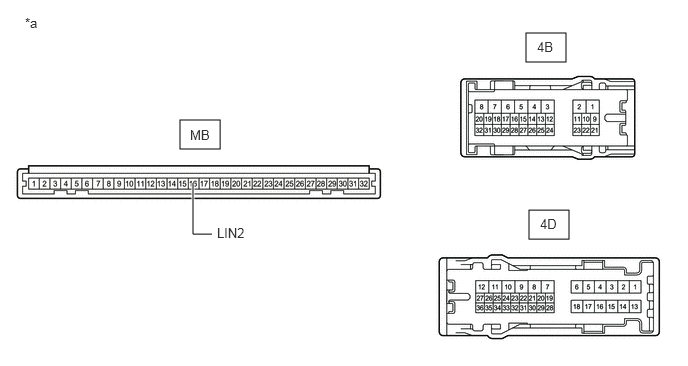
*a Component without harness connected
(Instrument Panel Junction Block Assembly)- - - Measure the resistance according to the value(s) in the table below.
HINT:
This inspection is to check the LIN communication line in the instrument panel junction block assembly that connects the wire harness to the built-in main body ECU (multiplex network body ECU).
Standard Resistance
Tester Connection Condition Specified Condition 4B-17 or 4D-25 - 4B-3 Always 10 kΩ or higher MB-16 (LIN2) - Other terminals Always 10 kΩ or higher Result
Proceed to OK NG
Result:
NG
REPLACE INSTRUMENT PANEL JUNCTION BLOCK ASSEMBLY. Refer to REMOVAL [12/2019 - 10/2022] , or refer to REMOVAL [10/2022 - 11/2023]
Result:
OK
See step 13
- Remove the instrument panel junction block assembly.
- CHECK MAIN BODY ECU (MULTIPLEX NETWORK BODY ECU)
- Install the main body ECU (multiplex network body ECU) to the instrument panel junction block assembly.
- Connect all instrument panel junction block assembly connectors other than 4B and 4D.
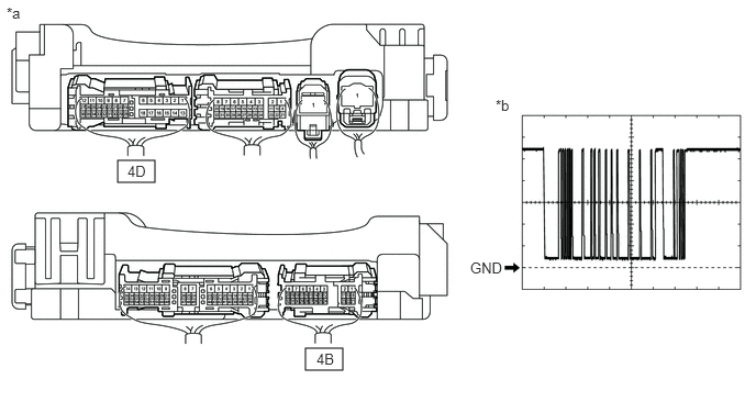
*a Component with harness connected
(Instrument Panel Junction Block Assembly)*b Waveform - Using a GTS, check the waveform.
HINT:
This inspection is to check the LIN communication line in the instrument panel junction block assembly that connects the wire harness to the built-in main body ECU (multiplex network body ECU).
OK
Tester Connection Condition Tool Setting Specified Condition 4B-17 - Body ground Ignition switch ON 2 V/DIV., 200 ms/DIV. Pulse generation
(See waveform)4D-25 - Body ground Ignition switch ON 2 V/DIV., 200 ms/DIV. Pulse generation
(See waveform)Result
Proceed to OK NG
Result:
OK
USE SIMULATION METHOD TO CHECK. Refer to HOW TO PROCEED WITH TROUBLESHOOTING [12/2019 - ]
Result:
NG
REPLACE MAIN BODY ECU (MULTIPLEX NETWORK BODY ECU). Refer to REMOVAL [12/2019 - 10/2022] , or refer to REMOVAL [10/2022 - 11/2023]
- CHECK HARNESS AND CONNECTOR (MULTIPLEX NETWORK MASTER SWITCH ASSEMBLY - POWER WINDOW REGULATOR MOTOR ASSEMBLY (DRIVER DOOR))
- Measure the resistance according to the value(s) in the table below.
Standard Resistance
Tester Connection Condition Specified Condition J18-16 (LIN2) - Body ground Always 10 kΩ or higher J18-16 (LIN2) - Other terminals Always 10 kΩ or higher Result
Proceed to OK NG
Result:
OK
REPLACE MULTIPLEX NETWORK MASTER SWITCH ASSEMBLY. Refer to REMOVAL [12/2019 - ]
Result:
NG
REPAIR OR REPLACE HARNESS OR CONNECTOR
- Measure the resistance according to the value(s) in the table below.