DTC P15AD-87: Active Grille Air Shutter "A" Missing Message [11/2023 - ]: Procedure
- PERFORM UTILITY USING GTS (SWITCH GRILLE SHUTTER CONTROL MODE)
- According to the display on the GTS, change the grille shutter control mode from normal mode to maintenance mode.
Powertrain > Engine > Utility
Tester Display Switch Grille Shutter Control Mode Result
Proceed to NEXT
Result:
NEXT
See step 2
- According to the display on the GTS, change the grille shutter control mode from normal mode to maintenance mode.
- CHECK HARNESS AND CONNECTOR (SWING GRILLE ACTUATOR ASSEMBLY - ECM)
- Disconnect the swing grille actuator assembly connector.
- Disconnect the ECM connector.
- Measure the resistance according to the value(s) in the table below.
Standard Resistance
Tester Connection Condition Specified Condition X1-2 (LIN) - C55-62 (LIN) Always Below 1 Ω X1-2 (LIN) or C55-62 (LIN) - Body ground and other terminals Always 10 kΩ or higher HINT:
Other parts that are connected between the tester connection terminals may affect the measurement value. Conduct the inspection after disconnecting them if the result is not as specified.
Result
Proceed to OK NG
Result:
NG
REPAIR OR REPLACE HARNESS OR CONNECTOR
Result:
OK
See step 3
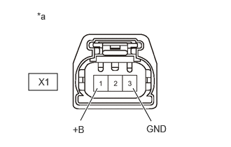
- CHECK TERMINAL VOLTAGE (POWER SOURCE OF SWING GRILLE ACTUATOR ASSEMBLY)
*a Front view of wire harness connector
(to Swing Grille Actuator Assembly)- Disconnect the swing grille actuator assembly connector.
- Turn the ignition switch to ON.
- Measure the voltage according to the value(s) in the table below.
Standard Voltage
Tester Connection Condition Specified Condition X1-1 (+B) - X1-3 (GND) Ignition switch to ON 11 to 14 V HINT:
Perform "Switch Grille Shutter Control Mode and Grille Shutter Initialization" after replacing the radiator shutter assembly.
Refer to INITIALIZATION [10/2021 - ]
Result
Proceed to OK NG
Result:
OK
REPLACE RADIATOR SHUTTER ASSEMBLY
Refer to REMOVAL [10/2021 - ]
Result:
NG
See step 4
- CHECK HARNESS AND CONNECTOR (SWING GRILLE ACTUATOR ASSEMBLY - BODY GROUND)
- Disconnect the swing grille actuator assembly connector.
- Measure the resistance according to the value(s) in the table below.
Standard Resistance
Tester Connection Condition Specified Condition X1-3 (GND) - Body ground Always Below 1 Ω Result
Proceed to OK NG
Result:
NG
REPAIR OR REPLACE HARNESS OR CONNECTOR
Result:
OK
See step 5
- CHECK HARNESS AND CONNECTOR (SWING GRILLE ACTUATOR ASSEMBLY - EFI-MAIN NO. 1 RELAY)
- Disconnect the swing grille actuator assembly connector.
- Remove the EFI-MAIN NO. 1, VVT, EFI-MAIN NO. 2 and EFI-MAIN NO. 3 relays from the No. 1 engine room relay block and No. 1 junction block assembly.
HINT:
Remove the VVT, EFI-MAIN NO. 2 and EFI-MAIN NO. 3 relays connected between the checked terminals as the coil inside the relay influences the measurement value.
- Measure the resistance according to the value(s) in the table below.
Standard Resistance
Tester Connection Condition Specified Condition X1-1 (+B) - 5 (EFI-MAIN NO. 1 Relay) Always Below 1 Ω X1-1 (+B) or 5 (EFI-MAIN NO. 1 Relay) - Body ground and other terminals Always 10 kΩ or higher Result
Proceed to OK NG
Result:
NG
REPAIR OR REPLACE HARNESS OR CONNECTOR
Result:
OK
See step 6
- CHECK ECM POWER SOURCE CIRCUIT
- Check the ECM power source circuit.
Refer to ECM Power Source Circuit [11/2023 - ]
Result
Proceed to NEXT
Result:
NEXT
See step 7
- Check the ECM power source circuit.
- READ VALUE USING GTS (GRILLE SHUTTER CONTROL MODE)
- According to the display on the GTS, change the grille shutter control mode from maintenance mode to normal mode.
Powertrain > Engine > Utility
Tester Display Switch Grille Shutter Control Mode - Read the value displayed on the GTS.
Powertrain > Engine > Data List
Tester Display Grille Shutter Control Mode Standard
GTS Display Specified Condition Grille Shutter Control Mode Normal Result
Proceed to NEXT
Result:
NEXT
END
- According to the display on the GTS, change the grille shutter control mode from maintenance mode to normal mode.