DTC P12D4-19: Fuel Pump Control Circuit Current Above Threshold; DTC P12D4-1D: Fuel Pump Control Circuit Current Out of Range [11/2024 - ]: Procedure
- INSPECT FUEL PUMP CONTROL ECU
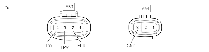
*a Component without harness connected
(Fuel Pump Control ECU)- - - Remove the fuel pump control ECU.
Refer to REMOVAL [12/2019 - ]
- Measure the resistance according to the value(s) in the table below.
Standard Resistance
Tester Connection Condition Specified Condition M53-2 (FPU) - M54-3 (GND) Always 2 kΩ or higher M53-3 (FPV) - M54-3 (GND) Always 2 kΩ or higher M53-4 (FPW) - M54-3 (GND) Always 2 kΩ or higher HINT:
This procedure checks for an internal short of the fuel pump control ECU when its transistor is stuck on.
Result
Proceed to OK NG
Result:
NG
REPLACE FUEL PUMP CONTROL ECU
Refer to REMOVAL [12/2019 - ]
Result:
OK
See step 2
- Remove the fuel pump control ECU.
- PERFORM ACTIVE TEST USING GTS (FUEL PUMP SINGLE PHASE ENERGIZATION)
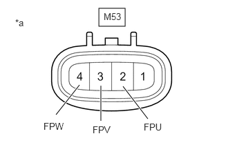
*a Component without harness connected
(Fuel Pump Control ECU)- Disconnect the M53 fuel pump control ECU connector.
- Operate the fuel pump control ECU using the Active Test function and measure the voltage according to the value(s) in the table below.
Powertrain > Engine > Active Test
Tester Display Fuel Pump Single Phase Energization Standard Voltage
Tester Connection GTS Operation Specified Condition M53-2 (FPU) - Body ground U Phase 4.4 to 8.4 V* M53-3 (FPV) - Body ground 8 to 15.5 V M53-4 (FPW) - Body ground 8 to 15.5 V M53-2 (FPU) - Body ground V Phase 8 to 15.5 V M53-3 (FPV) - Body ground 4.4 to 8.4 V* M53-4 (FPW) - Body ground 8 to 15.5 V M53-2 (FPU) - Body ground W Phase 8 to 15.5 V M53-3 (FPV) - Body ground 8 to 15.5 V M53-4 (FPW) - Body ground 4.4 to 8.4 V* HINT:
- *: This Active Test limits the fuel pump control ECU output duty cycle to 50%. Therefore, the output voltage of the fuel pump control ECU will be approximately 50% of the power source voltage (+B terminal).
- Before performing this inspection, check that the auxiliary battery voltage is between 11 and 14 V (not depleted).
Result
Proceed to OK NG
Result:
NG
REPLACE FUEL PUMP CONTROL ECU
Refer to REMOVAL [12/2019 - ]
Result:
OK
See step 3
- CHECK HARNESS AND CONNECTOR (FUEL PUMP CONTROL ECU - FUEL PUMP (FOR LOW PRESSURE SIDE))
- Disconnect the fuel pump control ECU connector.
- Disconnect the fuel pump (for low pressure side) connector.
- Measure the resistance according to the value(s) in the table below.
Standard Resistance
Tester Connection Condition Specified Condition M53-2 (FPU) or r2-3 (BLPU) - Other terminals Always 10 kΩ or higher M53-3 (FPV) or r2-4 (BLPV) - Other terminals Always 10 kΩ or higher M53-4 (FPW) or r2-2 (BLPW) - Other terminals Always 10 kΩ or higher Result
Proceed to OK NG
Result:
NG
REPAIR OR REPLACE HARNESS OR CONNECTOR
Result:
OK
See step 4
- REPLACE FUEL PUMP (FOR LOW PRESSURE SIDE)
Refer to REMOVAL [11/2023 - ]
HINT:
Perform "Inspection After Repair" after replacing the fuel pump (for low pressure side).
Refer to INITIALIZATION [10/2021 - ]
Result
Proceed to NEXT Result:
NEXT
See step 5
- CLEAR DTC
- Clear the DTCs.
Powertrain > Engine > Clear DTCs
- Turn the ignition switch off and wait for at least 30 seconds.
Result
Proceed to NEXT
Result:
NEXT
See step 6
- Clear the DTCs.
- CHECK WHETHER DTC OUTPUT RECURS (DTC P12D4-19 OR P12D4-1D)
- Drive the vehicle in accordance with the driving pattern described in Confirmation Driving Pattern.
- Read the DTCs.
Powertrain > Engine > Trouble Codes
OK
DTCs are not output.
Result
Proceed to NEXT
Result:
NEXT
END