DTC P0365-11: Camshaft Position Sensor "B" Bank 1 Circuit Short to Ground; DTC P0365-15: Camshaft Position Sensor "B" Bank 1 Circuit Short to Battery or Open [12/2019 - 10/2022]: Procedure
WARNING: This page is about a different variant/trim than selected.
- CHECK HARNESS AND CONNECTOR
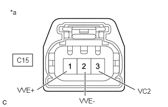
*a Front view of wire harness connector
(to Camshaft Position Sensor (for Exhaust Camshaft))HINT:
Make sure that the connector is properly connected. If it is not, securely connect it and check for DTCs again.
- Disconnect the camshaft position sensor (for exhaust camshaft) connector.
- Turn the ignition switch to ON.
- Measure the voltage according to the value(s) in the table below.
Standard Voltage
Tester Connection Condition Specified Condition C15-3 (VC2) - Body ground Ignition switch ON 4.5 to 5.5 V C15-1 (VVE+) - Body ground Ignition switch ON 3.0 to 5.0 V - Turn the ignition switch off and wait for at least 30 seconds.
- Measure the resistance according to the value(s) in the table below.
Standard Resistance
Tester Connection Condition Specified Condition C15-3 (VC2) - C15-1 (VVE+) Ignition switch off 1.425 to 1.575 kΩ C15-2 (VVE-) - Body ground Always Below 1 Ω Result
Proceed to OK NG
Result:
OK
REPLACE CAMSHAFT POSITION SENSOR (FOR EXHAUST CAMSHAFT)
Refer to PROCEDURE - Step 3
Result:
NG
See step 2
- CHECK HARNESS AND CONNECTOR (CAMSHAFT POSITION SENSOR (FOR EXHAUST CAMSHAFT) - ECM)
- Disconnect the camshaft position sensor (for exhaust camshaft) connector.
- Disconnect the ECM connector.
- Measure the resistance according to the value(s) in the table below.
Standard Resistance
Tester Connection Condition Specified Condition C15-1 (VVE+) - C55-91 (EV1+) Always Below 1 Ω C15-2 (VVE-) - C55-114 (EV1-) Always Below 1 Ω C15-3 (VC2) - C55-113 (VCE1) Always Below 1 Ω C15-1 (VVE+) or C55-91 (EV1+) - Body ground and other terminals Always 10 kΩ or higher C15-2 (VVE-) or C55-114 (EV1-) - Body ground and other terminals Always 10 kΩ or higher C15-3 (VC2) or C55-113 (VCE1) - Body ground and other terminals Always 10 kΩ or higher Result
Proceed to OK NG
Result:
OK
REPLACE ECM
Refer to REMOVAL [12/2019 - 10/2022]
Result:
NG
REPAIR OR REPLACE HARNESS OR CONNECTOR