Caution / Notice / Hint
HINT:
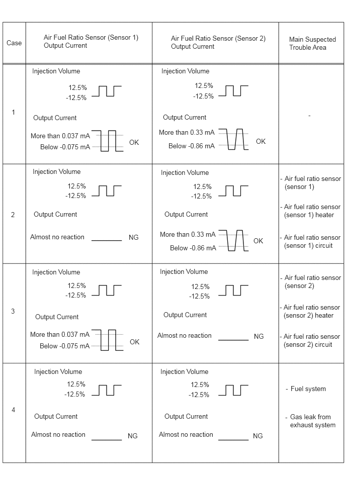
Malfunctioning areas can be identified by performing the Active Test "Control the Injection Volume for A/F Sensor". This Active Test can help to determine whether the air fuel ratio sensors (sensor 1 and sensor 2) and other potential trouble areas are malfunctioning.
The following procedure describes how to perform the Active Test "Control the Injection Volume for A/F Sensor" using the GTS.
- Connect the GTS to the DLC3.
- Turn the ignition switch to ON.
- Turn the GTS on.
- Put the engine in Inspection Mode (Maintenance Mode).
- Start the engine and warm it up until the engine coolant temperature is 75°C (167°F) or higher.
- Idle the engine for 5 minutes or more with the shift lever in P.
- Enter the following menus: Powertrain / Engine / Active Test / Control the Injection Volume for A/F Sensor / Data List / A/F (O2) Sensor Current B1S1 and A/F (O2) Sensor Current B1S2.
- Perform the Active Test with the engine idling (change the fuel injection volume).
- Monitor the output current of the air fuel ratio sensor (sensor 1) (A/F (O2) Sensor Current B1S1) and air fuel ratio sensor (sensor 2) (A/F (O2) Sensor Current B1S2) displayed on the GTS.
HINT:
- The Active Test "Control the Injection Volume for A/F Sensor" can be used to lower the fuel injection volume by 12.5% or increase the injection volume by 12.5%.
- Each sensor reacts in accordance with the increase and decrease in the fuel injection volume.
| GTS Display (Sensor) | Injection Volume | Status | Current |
|---|---|---|---|
| A/F (O2) Sensor Current B1S1 (Air fuel ratio sensor (sensor 1)) |
12.5% | Rich | Below -0.075 mA |
| -12.5% | Lean | More than 0.037 mA | |
| A/F (O2) Sensor Current B1S2 (Air fuel ratio sensor (sensor 2)) |
12.5% | Rich | Below -0.86 mA |
| -12.5% | Lean | More than 0.33 mA |
The air fuel ratio sensor (sensor 1) has an output delay of a few seconds and the air fuel ratio sensor (sensor 2) has a maximum output delay of approximately 20 seconds.
Performing the Active Test "Control the Injection Volume for A/F Sensor" allows the output value of the air fuel ratio sensors (sensor 1 and sensor 2) to be checked and graphed.
- Inspect the fuses for circuits related to this system before performing the following procedure.
- Vehicle Control History may be stored in the hybrid vehicle control ECU if the engine is malfunctioning. Certain vehicle condition information is recorded when Vehicle Control History is stored. Reading the vehicle conditions recorded in both the Freeze Frame Data and Vehicle Control History can be useful for troubleshooting.
For AWD: Refer to VEHICLE CONTROL HISTORY [12/2019 - 11/2023]
For 2WD: Refer to VEHICLE CONTROL HISTORY [12/2019 - 11/2023]
(Select Powertrain in Health Check and then check the time stamp data.)
- If any "Engine Malfunction" Vehicle Control History item has been stored in the hybrid vehicle control ECU, make sure to clear it. However, as all Vehicle Control History items are cleared simultaneously, if any Vehicle Control History items other than "Engine Malfunction" are stored, make sure to perform any troubleshooting for them before clearing Vehicle Control History.
For AWD: Refer to VEHICLE CONTROL HISTORY [12/2019 - 11/2023]
For 2WD: Refer to VEHICLE CONTROL HISTORY [12/2019 - 11/2023]
HINT:
- Sensor 1 refers to the sensor closest to the engine assembly.
- Sensor 2 refers to the sensor farthest away from the engine assembly.
- Read Freeze Frame Data using the GTS. The ECM records vehicle and driving condition information as Freeze Frame Data the moment a DTC is stored. When troubleshooting, Freeze Frame Data can help determine if the vehicle was moving or stationary, if the engine was warmed up or not, if the air fuel ratio was lean or rich, and other data from the time the malfunction occurred.