Mirror Heater does not Operate with Rear Defogger Switch [12/2019 - 11/2023]: Procedure
- PERFORM ACTIVE TEST USING GTS
- Perform the Active Test according to the display on the GTS.
Body Electrical > Air Conditioner > Active Test
Tester Display Measurement Item Control Range Diagnostic Note Defogger Relay (Rear) Mirror Heater OFF or ON - Body Electrical > Air Conditioner > Active Test
Tester Display Defogger Relay (Rear) Result
Result Proceed to Mirror heater operation on both mirrors is not normal A Mirror heater operation on RH side mirror is not normal B Mirror heater operation on LH side mirror is not normal C
Result:
B
See step 7
Result:
C
See step 9
Result:
A
See step 2
- Perform the Active Test according to the display on the GTS.
- CHECK WINDOW DEFOGGER SYSTEM
- Check the window defogger system operation.
Refer to OPERATION CHECK [12/2019 - 11/2023]
OK
The window defogger system operates normally.
Result
Proceed to OK NG
Result:
NG
GO TO WINDOW DEFOGGER SYSTEM. Refer to HOW TO PROCEED WITH TROUBLESHOOTING [12/2019 - 11/2023]
Result:
OK
See step 3
- Check the window defogger system operation.
- INSPECT MIR HTR RELAY
- Remove the MIR HTR relay from no. 1 engine room relay block and no. 1 junction block assembly.
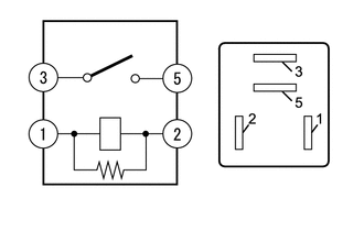
- Inspect the MIR HTR relay.
- Measure the resistance according to the value(s) in the table below.
Standard Resistance
Tester Connection Condition Specified Condition 3 - 5 Auxiliary battery voltage applied between terminals 1 and 2 Below 1 Ω 3 - 5 Auxiliary battery voltage not applied between terminals 1 and 2 10 kΩ or higher
Result
Proceed to OK NG - Measure the resistance according to the value(s) in the table below.
Result:
NG
REPLACE MIR HTR RELAY
Result:
OK
See step 4
- CHECK HARNESS AND CONNECTOR (MIR HTR RELAY POWER SOURCE AND BODY GROUND)
- Measure the voltage according to the value(s) in the table below.
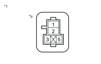
*1 No. 1 Engine Room Relay Block and No. 1 Junction Block Assembly *a MIR HTR Relay holder terminals Standard Voltage
Tester Connection Condition Specified Condition MIR HTR relay holder terminal 5 - Body ground Ignition switch off*1
Always*211 to 14 V - *1: for HV Model
- *2: for Gasoline Model
- Measure the resistance according to the value(s) in the table below.
Standard Resistance
Tester Connection Condition Specified Condition MIR HTR relay holder terminal 1 - Body ground Always Below 1 Ω Result
Proceed to OK NG
Result:
NG
REPAIR OR REPLACE HARNESS OR CONNECTOR
Result:
OK
See step 5
- Measure the voltage according to the value(s) in the table below.
- CHECK HARNESS AND CONNECTOR (DEF RELAY - MIR HTR RELAY)
- Remove the DEF relay from No. 1 engine room relay block and No. 1 junction block assembly.
- Measure the resistance according to the value(s) in the table below.
Standard Resistance
Tester Connection Condition Specified Condition DEF relay holder terminal 3 - MIR HTR relay holder terminal 2 Always Below 1 Ω DEF relay holder terminal 3 or MIR HTR relay terminal 2 - Body ground Always 10 kΩ or higher Result
Proceed to OK NG
Result:
NG
REPAIR OR REPLACE HARNESS OR CONNECTOR
Result:
OK
See step 6
- CHECK HARNESS AND CONNECTOR (OUTER REAR VIEW MIRROR ASSEMBLY LH/RH - MIR HTR RELAY AND BODY GROUND)
- Disconnect the J31 outer rear view mirror assembly LH connector.
- Disconnect the J15 outer rear view mirror assembly RH connector.
- Measure the resistance according to the value(s) in the table below.
Standard Resistance
Tester Connection Condition Specified Condition J31-6 (+) - MIR HTR relay holder terminal 3 Always Below 1 Ω J31-6 (+) or MIR HTR relay holder terminal 3 - Body ground Always 10 kΩ or higher J31-11 (E) - Body ground Always Below 1 Ω J15-6 (+) - MIR HTR relay holder terminal 3 Always Below 1 Ω J15-6 (+) or MIR HTR relay holder terminal 3 - Body ground Always 10 kΩ or higher J15-11 (E) - Body ground Always Below 1 Ω Result
Proceed to OK NG
Result:
OK
USE SIMULATION METHOD TO CHECK. Refer to HOW TO PROCEED WITH TROUBLESHOOTING [12/2019 - ]
Result:
NG
REPAIR OR REPLACE HARNESS OR CONNECTOR
- CHECK HARNESS AND CONNECTOR (OUTER REAR VIEW MIRROR ASSEMBLY RH - MIR HTR RELAY AND BODY GROUND)
- Remove the MIR HTR relay from the No. 1 engine room relay block and No. 1 junction block assembly.
- Disconnect the J31 outer rear view mirror assembly LH connector.
- Disconnect the J15 outer rear view mirror assembly RH connector.
- Measure the resistance according to the value(s) in the table below.
Standard Resistance
Tester Connection Condition Specified Condition J15-6 (+) - MIR HTR relay holder terminal 3 Always Below 1 Ω J15-11 (E) - Body ground Always Below 1 Ω J15-6 (+) or MIR HTR relay holder terminal 3 - Body ground Always 10 kΩ or higher Result
Proceed to OK NG
Result:
NG
REPAIR OR REPLACE HARNESS OR CONNECTOR
Result:
OK
See step 8
- INSPECT OUTER MIRROR RH
Refer to INSPECTION [12/2019 - ]
OK
Outer mirror RH is normal.
Result
Proceed to OK NG Result:
OK
REPLACE OUTER REAR VIEW MIRROR ASSEMBLY RH. Refer to REMOVAL [12/2019 - 11/2023]
Result:
NG
REPLACE OUTER MIRROR RH. Refer to REMOVAL [12/2019 - ]
- CHECK HARNESS AND CONNECTOR (OUTER REAR VIEW MIRROR ASSEMBLY LH - DEF RELAY AND BODY GROUND)
- Remove the MIR HTR relay from the No. 1 engine room relay block and No. 1 junction block assembly.
- Disconnect the J31 outer rear view mirror assembly LH connector.
- Disconnect the J15 outer rear view mirror assembly RH connector.
- Measure the resistance according to the value(s) in the table below.
Standard Resistance
Tester Connection Condition Specified Condition J31-6 (+) - MIR HTR relay holder terminal 3 Always Below 1 Ω J31-11 (E) - Body ground Always Below 1 Ω J31-6 (+) or MIR HTR relay holder terminal 3 - Body ground Always 10 kΩ or higher Result
Proceed to OK NG
Result:
NG
REPAIR OR REPLACE HARNESS OR CONNECTOR
Result:
OK
See step 10
- INSPECT OUTER MIRROR LH
Refer to INSPECTION [12/2019 - ]
OK
Outer mirror LH is normal.
Result
Proceed to OK NG Result:
OK
REPLACE OUTER REAR VIEW MIRROR ASSEMBLY LH. Refer to REMOVAL [12/2019 - 11/2023]
Result:
NG
REPLACE OUTER MIRROR LH. Refer to REMOVAL [12/2019 - ]