Terminals Of Ecu [12/2019 - 10/2022]
HINT:
Check from the rear of the connector while it is connected to the components.
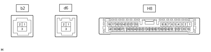
- INTEGRATION CONTROL SUB-ASSEMBLY
Terminal No. (Symbol) Terminal Description Condition Specified Condition H8-1 (B) - H8-20 (GND) Power source (+B) Always*3
Ignition switch off*411 to 14 V*1
10.5 to 16 V*2H8-3 (ACC) - H8-20 (GND) Power source (ACC) Ignition switch off Below 1 V Ignition switch ACC 11 to 14 V*1
10.5 to 16 V*2H8-4 (IG+) - H8-20 (GND) Power source (IG) Ignition switch off Below 1 V Ignition switch ON 11 to 14 V*1
10.5 to 16 V*2H8-5 (ILL+) - H8-20 (GND) Illumination signal Light control switch off Light control switch in tail or head position Ignition switch off
Light control switch in tail or head position11 to 14 V*1
10.5 to 16 V*2H8-17 (VMTR) - H8-20 (GND) Visual mute signal Ignition switch ACC
Screen display changing3.5 V or higher → Below 1 V → 3.5 V or higher H8-18 (TX+) - H8-20 (GND) AVC-LAN communication signal - - H8-20 (GND) - Body ground Ground Always Below 1 Ω H8-31 (CANN) CAN communication signal - - H8-32 (CANP) CAN communication signal - - H8-35 (TX1-) AVC-LAN communication signal - - H8-36 (TX1+) AVC-LAN communication signal - - H8-39 (VMTI) - H8-20 (GND) Visual mute signal Ignition switch ACC
Screen display changing3.5 V or higher → Below 1 V → 3.5 V or higher H8-40 (TX-) - H8-20 (GND) AVC-LAN communication signal - - b2-1 (GV+) Video signal (Digital) - - b2-2 (GV-) Video signal (Digital) - - b2-3 (GVG) - Body ground Shield ground Always Below 1 Ω d6-1 (GV+) Video signal (Digital) - - d6-2 (GV-) Video signal (Digital) - - d6-3 (GVG) - Body ground Shield ground Always Below 1 Ω *1: w/o Stop and Start System
*2: w/ Stop and Start System
*3: for Gasoline Model*4: for HV Model
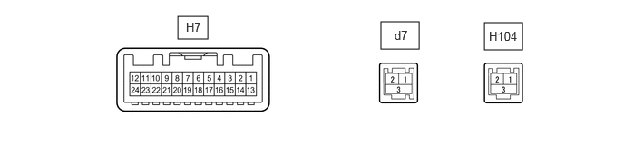
- MULTI-DISPLAY ASSEMBLY
Terminal No. (Symbol) Terminal Description Condition Specified Condition H7-1 (CSW+) - H7-13 (GND1) Terminal required by law Panoramic image being displayed 0 to 2 V Panoramic image not being displayed 5.5 to 7.05 V H7-2 (ILL+) - H7-13 (GND1) Illumination signal Light control switch off Below 1 V Ignition switch off
Light control switch in tail or head position11 to 14 V H7-7 (TX+) AVC-LAN communication signal - - H7-11 (VMTI) - H7-13 (GND1) Visual mute signal When image on display switches 3.5 V or higher
→ Below 1 V
→ 3.5 V or higherH7-12 (B) - H7-13 (GND1) Power source (+B) Ignition switch off*1
Always*211 to 14 V*3
10.5 to 16 V*4H7-13 (GND1) - Body ground Ground Always Below 1 Ω H7-19 (TX-) AVC-LAN communication signal - - H7-24 (ACC) - H7-13 (GND1) Power source (ACC) Ignition switch off Below 1 V Ignition switch ACC 11 to 14 V*3
10.5 to 16 V*4d7-1 (GVI-) Video signal (Digital) - - d7-2 (GVI+) Video signal (Digital) - - d7-3 (GVG1) Shield ground - - H104-1 (GV+) Video signal (Digital) - - H104-2 (GV-) Video signal (Digital) - - H104-3 (GND) Shield ground - - *1: for HV Model
*2: for Gasoline Model
*3: w/o Stop and Start System
*4: w/ Stop and Start System
- RADIO RECEIVER ASSEMBLY
Refer to TERMINALS OF ECU [12/2019 - 10/2022]