Power Source Circuit [12/2019 - 10/2022]: Procedure
- CHECK HARNESS AND CONNECTOR (INTEGRATION CONTROL SUB-ASSEMBLY POWER SOURCE)
- Disconnect the H8 integration control sub-assembly connector.
- Measure the resistance according to the value(s) in the table below.
Standard Resistance
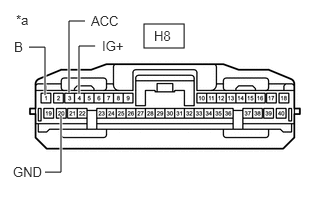
Tester Connection Condition Specified Condition H8-20 (GND) - Body ground Always Below 1 Ω *a Front view of wire harness connector
(to Integration Control Sub-assembly) - Measure the voltage according to the value(s) in the table below.
Standard Voltage
Tester Connection Condition Specified Condition H8-1 (B) - H8-20 (GND) Always*3
Ignition switch off*411 to 14 V*1
10.5 to 16 V*2H8-3 (ACC) - H8-20 (GND) Ignition switch ACC 11 to 14 V*1
10.5 to 16 V*2G3-4 (IG+) - H8-20 (GND) Ignition switch ON 11 to 14 V*1
10.5 to 16 V*2*1: w/o Stop and Start System
*2: w/ Stop and Start System
*3: for Gasoline Model
*4: for HV Model
Result
Result Proceed to OK A NG (w/o Stop and Start System) B NG (w/ Stop and Start System) C
Result:
A
PROCEED TO NEXT SUSPECTED AREA SHOWN IN PROBLEM SYMPTOMS TABLE. Refer to PROBLEM SYMPTOMS TABLE [12/2019 - 10/2022]
Result:
B
REPAIR OR REPLACE HARNESS OR CONNECTOR
Result:
C
GO TO STOP AND START SYSTEM. Refer to HOW TO PROCEED WITH TROUBLESHOOTING [12/2019 - 10/2022]