Visual Mute Signal Circuit between Radio Receiver and Multi-display [12/2019 - 10/2022]: Procedure
- INSPECT INTEGRATION CONTROL SUB-ASSEMBLY
- Measure the voltage according to the value(s) in the table below.
Standard Voltage
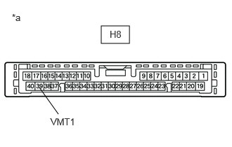
Tester Connection Condition Specified Condition H8-39 (VMT1) - Body ground Ignition switch ACC
Screen display changing3.5 V or higher
→ Below 1 V
→ 3.5 V or higher*a Component with harness connected
(Integration Control Sub-assembly)Result
Proceed to OK NG
Result:
NG
See step 5
Result:
OK
See step 2
- Measure the voltage according to the value(s) in the table below.
- INSPECT MULTI-DISPLAY ASSEMBLY
- Measure the voltage according to the value(s) in the table below.
Standard Voltage
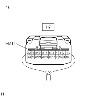
Tester Connection Condition Specified Condition H7-11 (VMTI) - Body ground Ignition switch ACC
Screen display changing3.5 V or higher
→ Below 1 V
→ 3.5 V or higher*a Component with harness connected
(Multi-display Assembly)Result
Proceed to OK NG
Result:
OK
PROCEED TO NEXT SUSPECTED AREA SHOWN IN PROBLEM SYMPTOMS TABLE. Refer to PROBLEM SYMPTOMS TABLE [12/2019 - 10/2022]
Result:
NG
See step 3
- Measure the voltage according to the value(s) in the table below.
- CHECK HARNESS AND CONNECTOR (INTEGRATION CONTROL SUB-ASSEMBLY - MULTI-DISPLAY ASSEMBLY)
- Disconnect the H8 integration control sub-assembly connector.
- Disconnect the H7 multi-display assembly connector.
- Measure the resistance according to the value(s) in the table below.
Standard Resistance
Tester Connection Condition Specified Condition H8-17 (VMTR) - H7-11 (VMTI) Always Below 1 Ω H8-17 (VMTR) or H7-11 (VMTI) - Body ground Always 10 kΩ or higher Result
Proceed to OK NG
Result:
NG
REPAIR OR REPLACE HARNESS OR CONNECTOR
Result:
OK
See step 4
- REPLACE MULTI-DISPLAY ASSEMBLY
- Replace the multi-display assembly with a new or known good one.
Refer to REMOVAL [12/2019 - 10/2022]
- Check that the screen display is normal.
OK
Screen display is normal.
Result
Proceed to OK NG
Result:
OK
END
Result:
NG
REPLACE RADIO RECEIVER ASSEMBLY. Refer to REMOVAL [12/2019 - 10/2022]
- Replace the multi-display assembly with a new or known good one.
- CHECK HARNESS AND CONNECTOR (RADIO RECEIVER ASSEMBLY - INTEGRATION CONTROL SUB-ASSEMBLY)
- Disconnect the H5 radio receiver assembly connector.
- Disconnect the H8 integration control sub-assembly connector.
- Measure the resistance according to the value(s) in the table below.
Standard Resistance
Tester Connection Condition Specified Condition H5-1 (VMTF) - H8-39 (VMT1) Always Below 1 Ω H5-1 (VMTF) or H8-39 (VMT1) - Body ground Always 10 kΩ or higher Result
Proceed to OK NG
Result:
NG
REPAIR OR REPLACE HARNESS OR CONNECTOR
Result:
OK
See step 6
- REPLACE INTEGRATION CONTROL SUB-ASSEMBLY
- Replace the integration control sub-assembly with a new or known good one.
Refer to REMOVAL [12/2019 - 10/2022]
- Check that the screen display is normal.
OK
Screen display is normal.
Result
Proceed to OK NG
Result:
OK
END
Result:
NG
REPLACE RADIO RECEIVER ASSEMBLY. Refer to REMOVAL [12/2019 - 10/2022]
- Replace the integration control sub-assembly with a new or known good one.