DTC B15C3-71: Speaker Output Short Actuator Stuck [11/2023 - ]: Procedure
- CHECK MODEL
- Choose the model to be inspected.
Result
Result Proceed to w/o "JBL" Sound System with DCM (Telematics Transceiver) A w/o "JBL" Sound System without DCM (Telematics Transceiver) B w/ "JBL" Sound System with DCM (Telematics Transceiver) C w/ "JBL" Sound System without DCM (Telematics Transceiver) D
Result:
B
See step 10
Result:
C
See step 16
Result:
D
See step 27
Result:
A
See step 2
- Choose the model to be inspected.
- CHECK HARNESS AND CONNECTOR (RADIO AND DISPLAY RECEIVER ASSEMBLY - EACH SPEAKER OR DCM (TELEMATICS TRANSCEIVER))
- Disconnect the H9 radio and display receiver assembly connector.
- Disconnect the H12 DCM (telematics transceiver) connector.
- Disconnect the H73 front No. 2 speaker assembly LH connector.
- Disconnect the K6 and K1 rear speaker assembly connectors.
- Measure the resistance according to the value(s) in the table below.
Standard Resistance
Tester Connection Condition Specified Condition H9-1 (FR+) or H12-1 (SPI+) - Body ground Always 10 kΩ or higher H9-6 (FR-) or H12-2 (SPI-) - Body ground Always 10 kΩ or higher H9-2 (FL+) or H73-4 (TWL+) - Body ground Always 10 kΩ or higher H9-7 (FL-) or H73-2 (TWL-) - Body ground Always 10 kΩ or higher H9-4 (RR+) or K1-2 - Body ground Always 10 kΩ or higher H9-9 (RR-) or K1-1 - Body ground Always 10 kΩ or higher H9-3 (RL+) or K6-2 - Body ground Always 10 kΩ or higher H9-8 (RL-) or K6-1 - Body ground Always 10 kΩ or higher Result
Proceed to OK NG
Result:
NG
REPAIR OR REPLACE HARNESS OR CONNECTOR
Result:
OK
See step 3
- CHECK HARNESS AND CONNECTOR (DCM (TELEMATICS TRANSCEIVER) - FRONT NO. 2 SPEAKER ASSEMBLY RH)
- Disconnect the H12 DCM (telematics transceiver) connector.
- Disconnect the H117 front No. 2 speaker assembly RH connector.
- Measure the resistance according to the value(s) in the table below.
Standard Resistance
Tester Connection Condition Specified Condition H12-3 (SPO+) or H117-4 (+TW) - Body ground Always 10 kΩ or higher H12-4 (SPO-) or H117-2 (-TW) - Body ground Always 10 kΩ or higher Result
Proceed to OK NG
Result:
NG
REPAIR OR REPLACE HARNESS OR CONNECTOR
Result:
OK
See step 4
- CHECK HARNESS AND CONNECTOR (FRONT NO. 1 SPEAKER ASSEMBLY - FRONT NO. 2 SPEAKER ASSEMBLY)
- Disconnect the J1 and J17 front No. 1 speaker assembly connectors.
- Disconnect the H117 and H73 front No. 2 speaker assembly connectors.
- Measure the resistance according to the value(s) in the table below.
Standard Resistance
Tester Connection Condition Specified Condition J17-2 or H73-3 (+) - Body ground Always 10 kΩ or higher J17-1 or H73-1 (-) - Body ground Always 10 kΩ or higher J1-2 or H117-3 (+) - Body ground Always 10 kΩ or higher J1-1 or H117-1 (-) - Body ground Always 10 kΩ or higher Result
Proceed to OK NG
Result:
NG
REPAIR OR REPLACE HARNESS AND CONNECTOR
Result:
OK
See step 5
- INSPECT FRONT NO. 1 SPEAKER ASSEMBLY
Refer to INSPECTION [12/2019 - ]
Result
Proceed to OK NG Result:
NG
REPLACE FRONT NO. 1 SPEAKER ASSEMBLY. Refer to REMOVAL [12/2019 - ]
Result:
OK
See step 6
- INSPECT REAR SPEAKER ASSEMBLY
Refer to INSPECTION [12/2019 - ]
Result
Proceed to OK NG Result:
NG
REPLACE REAR SPEAKER ASSEMBLY. Refer to REMOVAL [12/2019 - ]
Result:
OK
See step 7
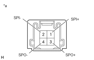
- INSPECT DCM (TELEMATICS TRANSCEIVER)
- Disconnect the telematics DCM (transceiver connector).
*a Component without harness connected
(DCM (Telematics Transceiver)) - Measure the resistance according to the value(s) in the table below.
Standard Resistance
Tester Connection Condition Specified Condition 1 (SPI+) - 3 (SPO+) Always Below 1 Ω 2 (SPI-) - 4 (SPO-) Always Below 1 Ω 1 (SPI+) - 2 (SPI-) Always 10 kΩ or higher 3 (SPO+) - 4 (SPO-) Always 10 kΩ or higher Result
Proceed to OK NG
Result:
NG
REPLACE DCM (TELEMATICS TRANSCEIVER). Refer to REMOVAL [11/2023 - ]
Result:
OK
See step 8
- Disconnect the telematics DCM (transceiver connector).
- REPLACE FRONT NO. 2 SPEAKER ASSEMBLY
- Replace the speaker assembly with a new or known good one.
Refer to REMOVAL [12/2019 - ]
Result
Proceed to NEXT
Result:
NEXT
See step 9
- Replace the speaker assembly with a new or known good one.
- CHECK FOR DTC
- Clear the DTCs.
Body Electrical > Navigation System > Clear DTCs
- Turn the ignition switch off.
- Check for DTCs and proceed to the following step.
Body Electrical > Navigation System > Trouble Codes
Result
Result Proceed to DTCs are not output A DTC B15C3-71 is output B
Result:
A
END
Result:
B
REPLACE RADIO AND DISPLAY RECEIVER ASSEMBLY. Refer to REMOVAL [11/2023 - ]
- Clear the DTCs.
- CHECK HARNESS AND CONNECTOR (RADIO AND DISPLAY RECEIVER ASSEMBLY - EACH SPEAKER)
- Disconnect the H9 radio and display receiver assembly connector.
- Disconnect the H117 and H73 front No. 2 speaker assembly connectors.
- Disconnect the K6 and K1 rear speaker assembly connectors.
- Measure the resistance according to the value(s) in the table below.
Standard Resistance
Tester Connection Condition Specified Condition H9-1 (FR+) or H117-4 (+TW) - Body ground Always 10 kΩ or higher H9-6 (FR-) or H117-2 (-TW) - Body ground Always 10 kΩ or higher H9-2 (FL+) or H73-4 (TWL+) - Body ground Always 10 kΩ or higher H9-7 (FL-) or H73-2 (TWL-) - Body ground Always 10 kΩ or higher H9-4 (RR+) or K1-2 - Body ground Always 10 kΩ or higher H9-9 (RR-) or K1-1 - Body ground Always 10 kΩ or higher H9-3 (RL+) or K6-2 - Body ground Always 10 kΩ or higher H9-8 (RL-) or K6-1 - Body ground Always 10 kΩ or higher Result
Proceed to OK NG
Result:
NG
REPAIR OR REPLACE HARNESS OR CONNECTOR
Result:
OK
See step 11
- CHECK HARNESS AND CONNECTOR (FRONT NO. 1 SPEAKER ASSEMBLY - FRONT NO. 2 SPEAKER ASSEMBLY)
- Disconnect the J1 and J17 front No. 1 speaker assembly connectors.
- Disconnect the H117 and H73 front No. 2 speaker assembly connectors.
- Measure the resistance according to the value(s) in the table below.
Standard Resistance
Tester Connection Condition Specified Condition J1-2 or H117-3 (+) - Body ground Always 10 kΩ or higher J1-1 or H117-1 (-) - Body ground Always 10 kΩ or higher J17-2 or H73-3 (+) - Body ground Always 10 kΩ or higher J17-1 or H73-1 (-) - Body ground Always 10 kΩ or higher Result
Proceed to OK NG
Result:
NG
REPAIR OR REPLACE HARNESS OR CONNECTOR
Result:
OK
See step 12
- INSPECT FRONT NO. 1 SPEAKER ASSEMBLY
Refer to INSPECTION [12/2019 - ]
Result
Proceed to OK NG Result:
NG
REPLACE FRONT NO. 1 SPEAKER ASSEMBLY. Refer to REMOVAL [12/2019 - ]
Result:
OK
See step 13
- INSPECT REAR SPEAKER ASSEMBLY
Refer to INSPECTION [12/2019 - ]
Result
Proceed to OK NG Result:
NG
REPLACE REAR SPEAKER ASSEMBLY. Refer to REMOVAL [12/2019 - ]
Result:
OK
See step 14
- REPLACE FRONT NO. 2 SPEAKER ASSEMBLY
- Replace the speaker assembly with a new or known good one.
Refer to REMOVAL [12/2019 - ]
Result
Proceed to NEXT
Result:
NEXT
See step 15
- Replace the speaker assembly with a new or known good one.
- CHECK FOR DTC
- Clear the DTCs.
Body Electrical > Navigation System > Clear DTCs
- Turn the ignition switch off.
- Check for DTCs and proceed to the following step.
Body Electrical > Navigation System > Trouble Codes
Result
Result Proceed to DTCs are not output A DTC B15C3-71 is output B
Result:
A
END
Result:
B
REPLACE RADIO AND DISPLAY RECEIVER ASSEMBLY. Refer to REMOVAL [11/2023 - ]
- Clear the DTCs.
- CHECK HARNESS AND CONNECTOR (STEREO COMPONENT AMPLIFIER ASSEMBLY - EACH SPEAKER, DCM (TELEMATICS TRANSCEIVER))
- Disconnect the M37 stereo component amplifier assembly connector.
- Disconnect the H12 DCM (telematics transceiver) connector.
- Disconnect the H74 and H72 front No. 2 speaker assembly connector.
- Disconnect the H13 and H14 front No. 3 speaker assembly connectors.
- Disconnect the K1 and K6 rear speaker assembly connectors.
- Disconnect the M36 rear No. 2 speaker assembly connector.
- Disconnect the W22 and W23 rear No. 3 speaker assembly connectors.
- Measure the resistance according to the value(s) in the table below.
Standard Resistance
Tester Connection Condition Specified Condition M37-13 (FR+) or H72-2 (TWR+) - Body ground Always 10 kΩ or higher M37-28 (FR-) or H72-1 (TWR-) - Body ground Always 10 kΩ or higher M37-12 (FL+) or H74-2 (TWL+) - Body ground Always 10 kΩ or higher M37-27 (FL-) or H74-1 (TWL-) - Body ground Always 10 kΩ or higher M37-9 (TWR+) or H12-1 (SPI+) - Body ground Always 10 kΩ or higher M37-24 (TWR-) or H12-2 (SPI-) - Body ground Always 10 kΩ or higher M37-8 (TWL+) or H14-3 (+) - Body ground Always 10 kΩ or higher M37-23 (TWL-) or H14-2 (-) - Body ground Always 10 kΩ or higher M37-15 (RR+) or K1-2 - Body ground Always 10 kΩ or higher M37-30 (RR-) or K1-1 - Body ground Always 10 kΩ or higher M37-14 (RL+) or K6-2 - Body ground Always 10 kΩ or higher M37-29 (RL-) or K6-1 - Body ground Always 10 kΩ or higher M37-6 (WF1+) or M36-4 (WF1+) - Body ground Always 10 kΩ or higher M37-21 (WF1-) or M36-3 (WF1-) - Body ground Always 10 kΩ or higher M37-5 (WF2+) or M36-2 (WF2+) - Body ground Always 10 kΩ or higher M37-20 (WF2-) or M36-1 (WF2-) - Body ground Always 10 kΩ or higher M37-11 (SR+) or W22-2 - Body ground Always 10 kΩ or higher M37-26 (SR-) or W22-1 - Body ground Always 10 kΩ or higher M37-10 (SL+) or W23-2 - Body ground Always 10 kΩ or higher M37-25 (SL-) or W23-1 - Body ground Always 10 kΩ or higher Result
Proceed to OK NG
Result:
NG
REPAIR OR REPLACE HARNESS OR CONNECTOR
Result:
OK
See step 17
- CHECK HARNESS AND CONNECTOR (DCM (TELEMATICS TRANSCEIVER) - FRONT NO. 3 SPEAKER ASSEMBLY)
- Disconnect the H12 DCM (telematics transceiver) connector.
- Disconnect the H13 front No. 3 speaker assembly RH connector.
- Measure the resistance according to the value(s) in the table below.
Standard Resistance
Tester Connection Condition Specified Condition H12-3 (SPO+) or H13-3 (+) - Body ground Always 10 kΩ or higher H12-4 (SPO-) or H13-2 (-) - Body ground Always 10 kΩ or higher Result
Proceed to OK NG
Result:
NG
REPAIR OR REPLACE HARNESS OR CONNECTOR
Result:
OK
See step 18
- CHECK HARNESS AND CONNECTOR (FRONT NO. 1 SPEAKER ASSEMBLY - FRONT NO. 3 SPEAKER ASSEMBLY)
- Disconnect the J1 and J17 front No. 1 speaker assembly connectors.
- Disconnect the H13 and H14 front No. 3 speaker assembly connectors.
- Measure the resistance according to the value(s) in the table below.
Standard Resistance
Tester Connection Condition Specified Condition J17-2 or H14-4 (+) - Body ground Always 10 kΩ or higher J17-1 or H14-1 (-) - Body ground Always 10 kΩ or higher J1-2 or H13-4 (+) - Body ground Always 10 kΩ or higher J1-1 or H13-1 (-) - Body ground Always 10 kΩ or higher Result
Proceed to OK NG
Result:
NG
REPAIR OR REPLACE HARNESS OR CONNECTOR
Result:
OK
See step 19
- INSPECT FRONT NO. 1 SPEAKER ASSEMBLY
Refer to INSPECTION [12/2019 - ]
Result
Proceed to OK NG Result:
NG
REPLACE FRONT NO. 1 SPEAKER ASSEMBLY. Refer to REMOVAL [12/2019 - ]
Result:
OK
See step 20
- INSPECT REAR SPEAKER ASSEMBLY
Refer to INSPECTION [12/2019 - ]
Result
Proceed to OK NG Result:
NG
REPLACE REAR SPEAKER ASSEMBLY. Refer to REMOVAL [12/2019 - ]
Result:
OK
See step 21
- INSPECT REAR NO. 2 SPEAKER ASSEMBLY
Refer to INSPECTION [12/2019 - ]
Result
Proceed to OK NG Result:
NG
REPLACE REAR NO. 2 SPEAKER ASSEMBLY. Refer to REMOVAL [12/2019 - ]
Result:
OK
See step 22
- INSPECT REAR NO. 3 SPEAKER ASSEMBLY
Refer to INSPECTION [12/2019 - ]
Result
Proceed to OK NG Result:
NG
REPLACE REAR NO. 3 SPEAKER ASSEMBLY. Refer to REMOVAL [12/2019 - ]
Result:
OK
See step 23
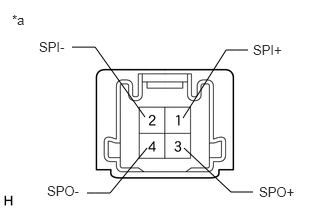
- INSPECT DCM (TELEMATICS TRANSCEIVER)
- Remove the DCM (telematics transceiver).
Refer to REMOVAL [11/2023 - ]
- Measure the resistance according to the value(s) in the table below.
*a Component without harness connected
(DCM (Telematics Transceiver))Standard Resistance
Tester Connection Condition Specified Condition 1 (SPI+) - 3 (SPO+) Always Below 1 Ω 2 (SPI-) - 4 (SPO-) Always Below 1 Ω 1 (SPI+) - 2 (SPI-) Always 10 kΩ or higher 3 (SPO+) - 4 (SPO-) Always 10 kΩ or higher 1 (SPI+) or 3 (SPO+) - Body ground Always 10 kΩ or higher 2 (SPI-) or 4 (SPO-) - Body ground Always 10 kΩ or higher Result
Proceed to OK NG
Result:
NG
REPLACE DCM (TELEMATICS TRANSCEIVER). Refer to REMOVAL [11/2023 - ]
Result:
OK
See step 24
- Remove the DCM (telematics transceiver).
- INSPECT FRONT NO. 2 SPEAKER ASSEMBLY
Refer to INSPECTION [12/2019 - ]
Result
Proceed to OK NG Result:
NG
REPLACE FRONT NO. 2 SPEAKER ASSEMBLY. Refer to REMOVAL [12/2019 - ]
Result:
OK
See step 25
- REPLACE FRONT NO. 3 SPEAKER ASSEMBLY
- Replace the speaker assembly with a new or known good one.
Refer to REMOVAL [12/2019 - ]
Result
Proceed to NEXT
Result:
NEXT
See step 26
- Replace the speaker assembly with a new or known good one.
- CHECK FOR DTC
- Clear the DTCs.
Body Electrical > Navigation System > Clear DTCs
- Turn the ignition switch off.
- Check for DTCs and proceed to the following step.
Body Electrical > Navigation System > Trouble Codes
Result
Result Proceed to DTCs are not output A DTC B15C3-71 is output B
Result:
A
END
Result:
B
REPLACE STEREO COMPONENT AMPLIFIER ASSEMBLY. Refer to REMOVAL [12/2019 - ]
- Clear the DTCs.
- CHECK HARNESS AND CONNECTOR (STEREO COMPONENT AMPLIFIER ASSEMBLY - EACH SPEAKER, DCM (TELEMATICS TRANSCEIVER))
- Disconnect the M37 stereo component amplifier assembly connector.
- Disconnect the H74 front No. 2 speaker assembly LH connector.
- Disconnect the H13 and H14 front No. 3 speaker assembly connectors.
- Disconnect the K1 and K6 rear speaker assembly connectors.
- Disconnect the M36 rear No. 2 speaker assembly connector.
- Disconnect the W22 and W23 rear No. 3 speaker assembly connectors.
- Measure the resistance according to the value(s) in the table below.
Standard Resistance
Tester Connection Condition Specified Condition M37-13 (FR+) or H72-2 (TWR+) - Body ground Always 10 kΩ or higher M37-28 (FR-) or H72-1 (TWR-) - Body ground Always 10 kΩ or higher M37-12 (FL+) or H74-2 (TWL+) - Body ground Always 10 kΩ or higher M37-27 (FL-) or H74-1 (TWL-) - Body ground Always 10 kΩ or higher M37-9 (TWR+) or H13-3 (+) - Body ground Always 10 kΩ or higher M37-24 (TWR-) or H13-2 (-) - Body ground Always 10 kΩ or higher M37-8 (TWL+) or H14-3 (+) - Body ground Always 10 kΩ or higher M37-23 (TWL-) or H14-2 (-) - Body ground Always 10 kΩ or higher M37-15 (RR+) or K1-2 - Body ground Always 10 kΩ or higher M37-30 (RR-) or K1-1 - Body ground Always 10 kΩ or higher M37-14 (RL+) or K6-2 - Body ground Always 10 kΩ or higher M37-29 (RL-) or K6-1 - Body ground Always 10 kΩ or higher M37-6 (WF1+) or M36-4 (WF1+) - Body ground Always 10 kΩ or higher M37-21 (WF1-) or M36-3 (WF1-) - Body ground Always 10 kΩ or higher M37-5 (WF2+) or M36-2 (WF2+) - Body ground Always 10 kΩ or higher M37-20 (WF2-) or M36-1 (WF2-) - Body ground Always 10 kΩ or higher M37-11 (SR+) or W22-2 - Body ground Always 10 kΩ or higher M37-26 (SR-) or W22-1 - Body ground Always 10 kΩ or higher M37-10 (SL+) or W23-2 - Body ground Always 10 kΩ or higher M37-25 (SL-) or W23-1 - Body ground Always 10 kΩ or higher Result
Proceed to OK NG
Result:
NG
REPAIR OR REPLACE HARNESS OR CONNECTOR
Result:
OK
See step 28
- CHECK HARNESS AND CONNECTOR (FRONT NO. 1 SPEAKER ASSEMBLY - FRONT NO. 3 SPEAKER ASSEMBLY)
- Disconnect the J1 and J17 front No. 1 speaker assembly connectors.
- Disconnect the H13 and H14 front No. 3 speaker assembly connectors.
- Measure the resistance according to the value(s) in the table below.
Standard Resistance
Tester Connection Condition Specified Condition J17-2 or H14-4 (+) - Body ground Always 10 kΩ or higher J17-1 or H14-1 (-) - Body ground Always 10 kΩ or higher J1-2 or H13-4 (+) - Body ground Always 10 kΩ or higher J1-1 or H13-1 (-) - Body ground Always 10 kΩ or higher Result
Proceed to OK NG
Result:
NG
REPAIR OR REPLACE HARNESS OR CONNECTOR
Result:
OK
See step 29
- INSPECT FRONT NO. 1 SPEAKER ASSEMBLY
Refer to INSPECTION [12/2019 - ]
Result
Proceed to OK NG Result:
NG
REPLACE FRONT NO. 1 SPEAKER ASSEMBLY. Refer to REMOVAL [12/2019 - ]
Result:
OK
See step 30
- INSPECT REAR SPEAKER ASSEMBLY
Refer to INSPECTION [12/2019 - ]
Result
Proceed to OK NG Result:
NG
REPLACE REAR SPEAKER ASSEMBLY. Refer to REMOVAL [12/2019 - ]
Result:
OK
See step 31
- INSPECT REAR NO. 2 SPEAKER ASSEMBLY
Refer to INSPECTION [12/2019 - ]
Result
Proceed to OK NG Result:
NG
REPLACE REAR NO. 2 SPEAKER ASSEMBLY. Refer to REMOVAL [12/2019 - ]
Result:
OK
See step 32
- INSPECT REAR NO. 3 SPEAKER ASSEMBLY
Refer to INSPECTION [12/2019 - ]
Result
Proceed to OK NG Result:
NG
REPLACE REAR NO. 3 SPEAKER ASSEMBLY. Refer to REMOVAL [12/2019 - ]
Result:
OK
See step 33
- INSPECT FRONT NO. 2 SPEAKER ASSEMBLY
Refer to INSPECTION [12/2019 - ]
Result
Proceed to OK NG Result:
NG
REPLACE FRONT NO. 2 SPEAKER ASSEMBLY. Refer to REMOVAL [12/2019 - ]
Result:
OK
See step 34
- REPLACE FRONT NO. 3 SPEAKER ASSEMBLY
- Replace the speaker assembly with a new or known good one.
Refer to REMOVAL [12/2019 - ]
Result
Proceed to NEXT
Result:
NEXT
See step 35
- Replace the speaker assembly with a new or known good one.
- CHECK FOR DTC
- Clear the DTCs.
Body Electrical > Navigation System > Clear DTCs
- Turn the ignition switch off.
- Check for DTCs and proceed to the following step.
Body Electrical > Navigation System > Trouble Codes
Result
Result Proceed to DTCs are not output A DTC B15C3-71 is output B
Result:
A
END
Result:
B
REPLACE STEREO COMPONENT AMPLIFIER ASSEMBLY. Refer to REMOVAL [12/2019 - ]
- Clear the DTCs.