DTC B15DB: Telematics Transceiver Disconnected [12/2019 - 10/2022]: Procedure
- CHECK HARNESS AND CONNECTOR (DCM (TELEMATICS TRANSCEIVER) POWER SOURCE)
- Disconnect the H11 DCM (telematics transceiver) connector.
- Measure the resistance according to the value(s) in the table below.
Standard Resistance
Tester Connection Condition Specified Condition H11-20 (E) - Body ground Always Below 1 Ω - Measure the voltage according to the value(s) in the table below.
Standard Voltage
Tester Connection Condition Specified Condition H11-1 (+B) - H11-20 (E)*1 Ignition switch off 11 to 14 V H11-1 (+B) - H11-20 (E)*2 Always 11 to 14 V*3
10.5 to 16 V*4H11-19 (IG2) - H11-20 (E) Ignition switch ON 11 to 14 V*3
10.5 to 16 V*4- *1: for HV Model
- *2: for Gasoline Model
- *3: w/o Stop and Start System
- *4: w/ Stop and Start System
Result
Result Proceed to OK A NG (w/o Stop and Start System) B NG (w/ Stop and Start System) C
Result:
B
REPAIR OR REPLACE HARNESS OR CONNECTOR
Result:
C
GO TO STOP AND START SYSTEM. Refer to HOW TO PROCEED WITH TROUBLESHOOTING [12/2019 - 10/2022]
Result:
A
See step 2
- INSPECT RADIO AND DISPLAY RECEIVER ASSEMBLY
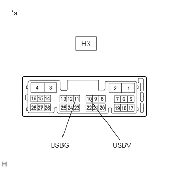
- Disconnect the H3 radio and display receiver assembly connector.
- Measure the resistance according to the value(s) in the table below.
*a Component without harness connected
(Radio and Display Receiver Assembly)Standard Resistance
Tester Connection Condition Specified Condition H3-11 (USBG) - Body ground Always Below 1 Ω - Measure the voltage according to the value(s) in the table below.
Standard Voltage
Tester Connection Condition Specified Condition H3-10 (USBV) - H3-11 (USBG) Ignition switch ACC 4.75 to 5.25 V Result
Proceed to OK NG
Result:
NG
REPLACE RADIO AND DISPLAY RECEIVER ASSEMBLY. Refer to REMOVAL [12/2019 - 10/2022]
Result:
OK
See step 3
- CHECK HARNESS AND CONNECTOR (RADIO AND DISPLAY RECEIVER ASSEMBLY - DCM (TELEMATICS TRANSCEIVER))
- Disconnect the H3 radio and display receiver assembly connector.
- Disconnect the H11 DCM (telematics transceiver) connector.
- Measure the resistance according to the value(s) in the table below.
Standard Resistance
Tester Connection Condition Specified Condition H3-10 (USBV) - H11-15 (USBV) Always Below 1 Ω H3-11 (USBG) - H11-31 (USBG) Always Below 1 Ω H3-10 (USBV) or H11-15 (USBV) - Body ground Always 10 kΩ or higher H3-11 (USBG) or H11-31 (USBG) - Body ground Always 10 kΩ or higher Result
Proceed to OK NG
Result:
NG
REPAIR OR REPLACE HARNESS OR CONNECTOR
Result:
OK
See step 4
- CHECK HARNESS AND CONNECTOR (DCM (TELEMATICS TRANSCEIVER) - RADIO AND DISPLAY RECEIVER ASSEMBLY)
- Check the installation condition.
- Check the USB communication lines between the radio and display receiver assembly and DCM (telematics transceiver) for any installation or connection problems.
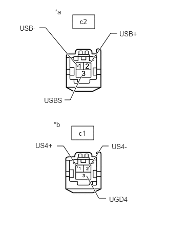
- Disconnect the c2 DCM (telematics transceiver) connector.
- Disconnect the c1 radio and display receiver assembly connector.
- Measure the resistance according to the value(s) in the table below.
Standard Resistance
Tester Connection Condition Specified Condition c2-2 (USB+) - c1-1 (US4+) Always Below 1 Ω c2-1 (USB-) - c1-2 (US4-) Always Below 1 Ω c2-3 (USBS) - c1-3 (UGD4) Always Below 1 Ω c2-2 (USB+) or c1-1 (US4+) - Body ground Always 10 kΩ or higher c2-1 (USB-) or c1-2 (US4-) - Body ground Always 10 kΩ or higher c2-3 (USBS) or c1-3 (UGD4) - Body ground Always 10 kΩ or higher *a Front view of wire harness connector
(to DCM (Telematics Transceiver))*b Front view of wire harness connector
(to Radio and Display Receiver Assembly)Result
Proceed to OK NG
Result:
NG
REPAIR OR REPLACE HARNESS OR CONNECTOR
Result:
OK
See step 5
- Check the installation condition.
- CHECK DCM (TELEMATICS TRANSCEIVER)
- Replace the DCM (telematics transceiver) with a new or known good one.
Refer to REMOVAL [12/2019 - 10/2022]
- Clear the DTCs.
Body Electrical > Navigation System > Clear DTCs
- Turn the ignition switch off.
- Turn the ignition switch to ON and wait for 90 seconds.
- Recheck for DTCs and check that no DTCs are output.
Body Electrical > Navigation System > Trouble Codes
OK
No DTCs are output.
Result
Proceed to OK NG
Result:
OK
END
Result:
NG
REPLACE RADIO AND DISPLAY RECEIVER ASSEMBLY. Refer to REMOVAL [12/2019 - 10/2022]
- Replace the DCM (telematics transceiver) with a new or known good one.