DTC B15DB-87: Telematics Transceiver Missing Message [11/2023 - ]: Procedure
- CHECK DTC
Pre-procedure1
- Clear the DTCs.
Body Electrical > Navigation System > Clear DTCs
Procedure1
- Check for DTCs.
Body Electrical > Navigation System > Trouble Codes
Result
Result Proceed to DTCs are not output OK DTCs are output NG Post-procedure1
- None
Result:
OK
USE SIMULATION METHOD TO CHECK
Refer to HOW TO PROCEED WITH TROUBLESHOOTING [12/2019 - ]
Result:
NG
See step 2
- Clear the DTCs.
- CHECK HARNESS AND CONNECTOR (DCM [TELEMATICS TRANSCEIVER] POWER SOURCE)
Pre-procedure1
- Disconnect the H11 DCM (telematics transceiver) connector.
Procedure1
- Measure the resistance according to the value(s) in the table below.
Standard Resistance
Tester Connection Condition Specified Condition H11-20 (E) - Body ground Always Below 1 Ω - Measure the voltage according to the value(s) in the table below.
Standard Voltage
Tester Connection Condition Specified Condition H11-1 (+B) - H11-20 (E) Ignition switch off 11 to 14 V*1
10.5 to 16 V*2H11-19 (IG2) - H11-20 (E) Ignition switch ON 11 to 14 V*1
10.5 to 16 V*2- *1: w/o Stop and Start System
- *2: w/ Stop and Start System
Result
Result Proceed to OK A NG (w/o Stop and Start System) B NG (w/ Stop and Start System) C Post-procedure1
- None
Result:
B
REPAIR OR REPLACE HARNESS OR CONNECTOR
Result:
C
GO TO STOP AND START SYSTEM
Refer to HOW TO PROCEED WITH TROUBLESHOOTING [10/2022 - ]
Result:
A
See step 3
- Disconnect the H11 DCM (telematics transceiver) connector.
- CHECK HARNESS AND CONNECTOR (RADIO AND DISPLAY RECEIVER ASSEMBLY - DCM [TELEMATICS TRANSCEIVER])
Pre-procedure1
- Disconnect the H108 radio and display receiver assembly connector.
- Disconnect the H11 DCM (telematics transceiver) connector.
Procedure1
- Measure the resistance according to the value(s) in the table below.
Standard Resistance
Tester Connection Condition Specified Condition H108-18 (USBV) - H11-15 (USBV) Always Below 1 Ω H108-17 (USBG) - H11-31 (USBG) Always Below 1 Ω H108-18 (USBV) - Body ground Always 10 kΩ or higher H108-17 (USBG) - Body ground Always 10 kΩ or higher Result
Proceed to OK NG Post-procedure1
- None
Result:
NG
REPAIR OR REPLACE HARNESS OR CONNECTOR
Result:
OK
See step 4
- INSPECT RADIO AND DISPLAY RECEIVER ASSEMBLY (USBV, USBG)
Pre-procedure1
- With the radio and display receiver assembly connectors connected, disconnect the H11 DCM (telematics transceiver) connector.
Procedure1
- Measure the resistance according to the value(s) in the table below.
Standard Resistance
Tester Connection Condition Specified Condition H11-31 (USBG) - Body ground Always Below 1 Ω - Measure the voltage according to the value(s) in the table below.
Standard Voltage
Tester Connection Switch Condition Specified Condition H11-15 (USBV) - H11-31 (USBG) Ignition switch ON 3 V or higher Result
Proceed to OK NG Post-procedure1
- None
Result:
NG
REPLACE RADIO AND DISPLAY RECEIVER ASSEMBLY
Refer to REMOVAL [11/2023 - ]
Result:
OK
See step 5
- With the radio and display receiver assembly connectors connected, disconnect the H11 DCM (telematics transceiver) connector.
- CHECK NO. 2 ANTENNA CORD SUB-ASSEMBLY (RADIO AND DISPLAY RECEIVER ASSEMBLY - DCM [TELEMATICS TRANSCEIVER])
Pre-procedure1
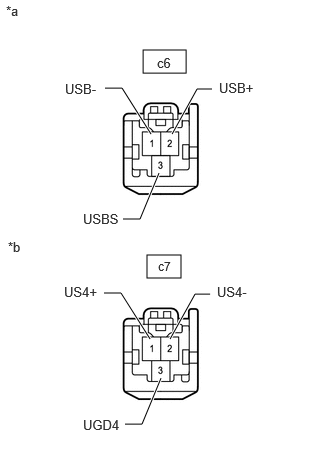
- Disconnect the c6 radio and display receiver assembly connector.
*a Front view of No. 2 antenna cord sub-assembly
(to Radio and Display Receiver Assembly)*b Front view of No. 2 antenna cord sub-assembly
(to DCM (Telematics Transceiver)) - Disconnect the c7 DCM (telematics transceiver) connector.
Procedure1
- Measure the resistance according to the value(s) in the table below.
Standard Resistance
Tester Connection Condition Specified Condition c6-1 (USB-) - c7-2 (US4+) Always Below 1 Ω c6-2 (USB+) - c7-1 (US4-) Always Below 1 Ω c6-3 (USBS) - c7-3 (UGD4) Always Below 1 Ω c6-1 (USB-) or c7-2 (US4+) - Body ground Always 10 kΩ or higher c6-2 (USB+) or c7-1 (US4-) - Body ground Always 10 kΩ or higher c6-3 (USBS) or c7-3 (UGD4) - Body ground Always 10 kΩ or higher Result
Proceed to OK NG Post-procedure1
- None
Result:
NG
REPLACE NO. 2 ANTENNA CORD SUB-ASSEMBLY
Refer to REMOVAL [11/2023 - 11/2024] , or refer to REMOVAL [11/2024 - ]
Result:
OK
See step 6
- Disconnect the c6 radio and display receiver assembly connector.
- REPLACE DCM (TELEMATICS TRANSCEIVER)
Pre-procedure1
- Replace the DCM (telematics transceiver) with a new one.
HINT:
Refer to REMOVAL [11/2023 - ]
- Clear the DTCs.
Body Electrical > Navigation System > Clear DTCs
Procedure1
- Check for DTCs.
Body Electrical > Navigation System > Trouble Codes
Result
Proceed to OK NG Post-procedure1
- None
Result:
OK
END (DCM [TELEMATICS TRANSCEIVER] IS DEFECTIVE)
Result:
NG
REPLACE RADIO AND DISPLAY RECEIVER ASSEMBLY
Refer to REMOVAL [11/2023 - ]
- Replace the DCM (telematics transceiver) with a new one.