Mute Signal Circuit between Radio Receiver and Telematics Transceiver [12/2019 - 10/2022]: Procedure
- INSPECT DCM (TELEMATICS TRANSCEIVER)
- Measure the voltage according to the value(s) in the table below.
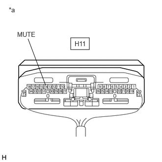
*a Component with harness connected
(DCM (Telematics Transceiver))Standard Voltage
Tester Connection Condition Specified Condition H11-14 (MUTE) - Body ground Ignition switch ACC
Audio system playing
→ Emergency call mode2 V or higher
→ Below 1 VResult
Proceed to OK NG
Result:
OK
PROCEED TO NEXT SUSPECTED AREA SHOWN IN PROBLEM SYMPTOMS TABLE. Refer to PROBLEM SYMPTOMS TABLE [12/2019 - 10/2022]
Result:
NG
See step 2
- Measure the voltage according to the value(s) in the table below.
- CHECK HARNESS AND CONNECTOR (RADIO AND DISPLAY RECEIVER ASSEMBLY - DCM (TELEMATICS TRANSCEIVER))
- Disconnect the H2 radio and display receiver assembly connector.
- Disconnect the H11 DCM (telematics transceiver) connector.
- Measure the resistance according to the value(s) in the table below.
Standard Resistance
Tester Connection Condition Specified Condition H2-3 (TMUT) - H11-14 (MUTE) Always Below 1 Ω H2-3 (TMUT) or H11-14 (MUTE) - Body ground Always 10 kΩ or higher Result
Proceed to OK NG
Result:
NG
REPAIR OR REPLACE HARNESS OR CONNECTOR
Result:
OK
See step 3
- INSPECT RADIO AND DISPLAY RECEIVER ASSEMBLY
- Disconnect the H11 DCM (telematics transceiver) connector.
- Measure the voltage according to the value(s) in the table below.
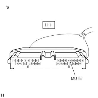
*a Front view of wire harness connector
(to DCM (Telematics Transceiver))Standard Voltage
Tester Connection Condition Specified Condition H11-14 (MUTE) - Body ground Ignition switch ACC 2 V or higher Result
Proceed to OK NG
Result:
OK
REPLACE DCM (TELEMATICS TRANSCEIVER). Refer to REMOVAL [12/2019 - 10/2022]
Result:
NG
REPLACE RADIO AND DISPLAY RECEIVER ASSEMBLY. Refer to REMOVAL [12/2019 - 10/2022]