Microphone Circuit [12/2019 - 10/2022]: Procedure
- CHECK MICROPHONE AND VOICE RECOGNITION (INPUT TO NAVIGATION ECU)
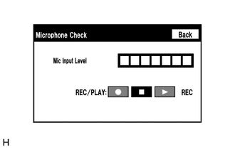
- Enter the "Microphone Check" screen. Refer to Check Microphone (Input to navigation ECU) in Operation Check.
Refer to OPERATION CHECK [12/2019 - 10/2022]
- When voice is input into the microphone, check that the microphone input level meter changes according to the input voice.
OK
Check results are normal.
Result
Proceed to OK NG
Result:
OK
PROCEED TO NEXT SUSPECTED AREA SHOWN IN PROBLEM SYMPTOMS TABLE. Refer to PROBLEM SYMPTOMS TABLE [12/2019 - 10/2022]
Result:
NG
See step 2
- Enter the "Microphone Check" screen. Refer to Check Microphone (Input to navigation ECU) in Operation Check.
- CHECK MICROPHONE AND VOICE RECOGNITION (INPUT TO RADIO AND DISPLAY RECEIVER ASSEMBLY)
- Enter the "Microphone Check" screen. Refer to Check Microphone (Input to radio and display receiver assembly) in Operation Check.
Refer to OPERATION CHECK [12/2019 - 10/2022]
- When voice is input into the microphone, check that the microphone input level meter changes according to the input voice.
OK
Check results are normal.
Result
Proceed to OK NG
Result:
NG
See step 5
Result:
OK
See step 3
- Enter the "Microphone Check" screen. Refer to Check Microphone (Input to radio and display receiver assembly) in Operation Check.
- CHECK HARNESS AND CONNECTOR (RADIO AND DISPLAY RECEIVER ASSEMBLY - NAVIGATION ECU)
- Disconnect the H3 radio and display receiver assembly connector.
- Disconnect the H18 navigation ECU connector.
- Measure the resistance according to the value(s) in the table below.
Standard Resistance
Tester Connection Condition Specified Condition H3-25 (MCO+) - H18-13 (MIC+) Always Below 1 Ω H3-26 (MCO-) - H18-14 (MIC-) Always Below 1 Ω H3-25 (MCO+) or H18-13 (MIC+) - Body ground Always 10 kΩ or higher H3-26 (MCO-) or H18-14 (MIC-) - Body ground Always 10 kΩ or higher H3-24 (SGND) - Body ground Always 10 kΩ or higher Result
Proceed to OK NG
Result:
NG
REPAIR OR REPLACE HARNESS OR CONNECTOR
Result:
OK
See step 4
- INSPECT RADIO AND DISPLAY RECEIVER ASSEMBLY (OUTPUT TO NAVIGATION ECU)
- Disconnect the H18 navigation ECU connector.
- Turn the ignition switch to ACC.
- Check the signal waveform according to the condition(s) in the table below.
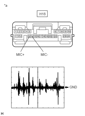
*a Front view of wire harness connector
(to Navigation ECU)Item Condition Measurement terminal H18-13 (MIC+) - H18-14 (MIC-) Tool setting 50 mV/DIV., 500 ms/DIV. Vehicle condition - Turn the ignition switch to ACC.
- Sound is input to the telephone microphone assembly when the user is closer than 125 mm from the telephone microphone assembly sound holes in the roof headlining holder cover.
OK
The waveform is similar to that shown in the illustration.
HINT:
The oscilloscope waveform shown in the illustration is an example for reference only.
Result
Proceed to OK NG
Result:
OK
PROCEED TO NEXT SUSPECTED AREA SHOWN IN PROBLEM SYMPTOMS TABLE. Refer to PROBLEM SYMPTOMS TABLE [12/2019 - 10/2022]
Result:
NG
REPLACE RADIO AND DISPLAY RECEIVER ASSEMBLY. Refer to REMOVAL [12/2019 - 10/2022]
- CHECK MODEL
- Check the model to be inspected.
Result
Result Proceed to w/o Telematics Transceiver A w/ Telematics Transceiver B
Result:
B
See step 9
Result:
A
See step 6
- Check the model to be inspected.
- CHECK HARNESS AND CONNECTOR (RADIO AND DISPLAY RECEIVER ASSEMBLY - TELEPHONE MICROPHONE ASSEMBLY)
- Disconnect the H2 radio and display receiver assembly connector.
- Disconnect the R12 telephone microphone assembly connector.
- Measure the resistance according to the value(s) in the table below.
Standard Resistance
Tester Connection Condition Specified Condition H2-25 (SNS2) - R12-3 (SNS2) Always Below 1 Ω H2-23 (MACC) - R12-1 (MACC) Always Below 1 Ω H2-21 (MIN+) - R12-2 (MCO+) Always Below 1 Ω H2-22 (MIN-) - R12-4 (MCO-) Always Below 1 Ω H2-25 (SNS2) or R12-3 (SNS2) - Body ground Always 10 kΩ or higher H2-23 (MACC) or R12-1 (MACC) - Body ground Always 10 kΩ or higher H2-21 (MIN+) or R12-2 (MCO+) - Body ground Always 10 kΩ or higher H2-22 (MIN-) or R12-4 (MCO-) - Body ground Always 10 kΩ or higher H2-24 (SGND) - Body ground Always 10 kΩ or higher Result
Proceed to OK NG
Result:
NG
REPAIR OR REPLACE HARNESS OR CONNECTOR
Result:
OK
See step 7
- CHECK RADIO AND DISPLAY RECEIVER ASSEMBLY
- Remove the radio and display receiver assembly with the connector(s) still connected.
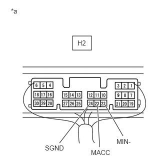
*a Component with harness connected
(Radio and Display Receiver Assembly) - Measure the voltage according to the value(s) in the table below.
Standard Voltage
Tester Connection Condition Specified Condition H2-23 (MACC) - Body ground Ignition switch ACC 4 to 6 V - Measure the resistance according to the value(s) in the table below.
Standard Resistance
Tester Connection Condition Specified Condition H2-22 (MIN-) - Body ground Always Below 1 Ω H2-24 (SGND) - Body ground Always Below 1 Ω Result
Proceed to OK NG
Result:
NG
REPLACE RADIO AND DISPLAY RECEIVER ASSEMBLY. Refer to REMOVAL [12/2019 - 10/2022]
Result:
OK
See step 8
- Remove the radio and display receiver assembly with the connector(s) still connected.
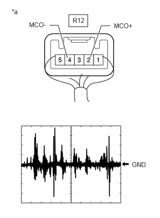
- CHECK TELEPHONE MICROPHONE ASSEMBLY (OUTPUT TO RADIO AND DISPLAY RECEIVER ASSEMBLY)
*a Component with harness connected
(Telephone Microphone Assembly)- Check the output waveform.
- Remove the telephone microphone assembly with the connector(s) still connected.
Refer to REMOVAL [12/2019 - 10/2022]
- Connect an oscilloscope to terminal R12-2 (MCO+) and R12-4 (MCO-).
- Turn the ignition switch to ACC.
- Sound is input to the telephone microphone assembly when the user is closer than 125 mm from the telephone microphone assembly sound holes in the roof headlining holder cover.
- Check the signal waveform according to the condition(s) in the table below.
Item Condition Measurement terminal R12-2 (MCO+) - R12-4 (MCO-) Tool setting 50 mV/DIV., 500 ms/DIV. Vehicle condition - Turn the ignition switch to ACC
- Sound is input to the telephone microphone assembly when the user is closer than 125 mm from the telephone microphone assembly sound holes in the roof headlining holder cover.
OK
The waveform is similar to that shown in the illustration.
HINT:
The oscilloscope waveform shown in the illustration is an example for reference only.
Result
Proceed to OK NG - Remove the telephone microphone assembly with the connector(s) still connected.
Result:
OK
REPLACE RADIO AND DISPLAY RECEIVER ASSEMBLY. Refer to REMOVAL [12/2019 - 10/2022]
Result:
NG
REPLACE TELEPHONE MICROPHONE ASSEMBLY. Refer to REMOVAL [12/2019 - 10/2022]
- Check the output waveform.
- CHECK HARNESS AND CONNECTOR (RADIO AND DISPLAY RECEIVER ASSEMBLY - TELEPHONE MICROPHONE ASSEMBLY)
- Disconnect the H2 radio and display receiver assembly connector.
- Disconnect the R12 telephone microphone assembly connector.
- Measure the resistance according to the value(s) in the table below.
Standard Resistance
Tester Connection Condition Specified Condition H2-25 (SNS2) - R12-3 (SNS2) Always Below 1 Ω H2-25 (SNS2) or R12-3 (SNS2) - Body ground Always 10 kΩ or higher Result
Proceed to OK NG
Result:
NG
REPAIR OR REPLACE HARNESS OR CONNECTOR
Result:
OK
See step 10
- CHECK HARNESS AND CONNECTOR (RADIO AND DISPLAY RECEIVER ASSEMBLY - DCM (TELEMATICS TRANSCEIVER))
- Disconnect the H2 radio and display receiver assembly connector.
- Disconnect the H11 DCM (telematics transceiver) connector.
- Measure the resistance according to the value(s) in the table below.
Standard Resistance
Tester Connection Condition Specified Condition H2-21 (MIN+) - H11-16 (MCO+) Always Below 1 Ω H2-22 (MIN-) - H11-32 (MCO-) Always Below 1 Ω H2-21 (MIN+) or H11-16 (MCO+) - Body ground Always 10 kΩ or higher H2-22 (MIN-) or H11-32 (MCO-) - Body ground Always 10 kΩ or higher H2-24 (SGND) - Body ground Always 10 kΩ or higher Result
Proceed to OK NG
Result:
NG
REPAIR OR REPLACE HARNESS OR CONNECTOR
Result:
OK
See step 11
- CHECK HARNESS AND CONNECTOR (DCM (TELEMATICS TRANSCEIVER) - TELEPHONE MICROPHONE ASSEMBLY)
- Disconnect the H11 DCM (telematics transceiver) connector.
- Disconnect the R12 telephone microphone assembly connector.
- Measure the resistance according to the value(s) in the table below.
Standard Resistance
Tester Connection Condition Specified Condition H11-5 (MCVD) - R12-1 (MACC) Always Below 1 Ω H11-6 (MCI+) - R12-2 (MCO+) Always Below 1 Ω H11-7 (MCI-) - R12-4 (MCO-) Always Below 1 Ω H11-5 (MCVD) or R12-1 (MACC) - Body ground Always 10 kΩ or higher H11-6 (MCI+) or R12-2 (MCO+) - Body ground Always 10 kΩ or higher H11-7 (MCI-) or R12-4 (MCO-) - Body ground Always 10 kΩ or higher H11-23 (SGND) - Body ground Always 10 kΩ or higher Result
Proceed to OK NG
Result:
NG
REPAIR OR REPLACE HARNESS OR CONNECTOR
Result:
OK
See step 12
- CHECK DCM (TELEMATICS TRANSCEIVER)
- Remove the DCM (telematics transceiver) with the connector(s) still connected.
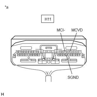
*a Component with harness connected
(DCM (Telematics Transceiver)) - Measure the voltage according to the value(s) in the table below.
Standard Voltage
Tester Connection Condition Specified Condition H11-5 (MCVD) - Body ground Ignition switch ACC 4 to 6 V - Measure the resistance according to the value(s) in the table below.
Standard Resistance
Tester Connection Condition Specified Condition H11-23 (SGND) - Body ground Always Below 1 Ω H11-7 (MCI-) - Body ground Always Below 1 Ω Result
Proceed to OK NG
Result:
NG
REPLACE DCM (TELEMATICS TRANSCEIVER). Refer to REMOVAL [12/2019 - 10/2022]
Result:
OK
See step 13
- Remove the DCM (telematics transceiver) with the connector(s) still connected.
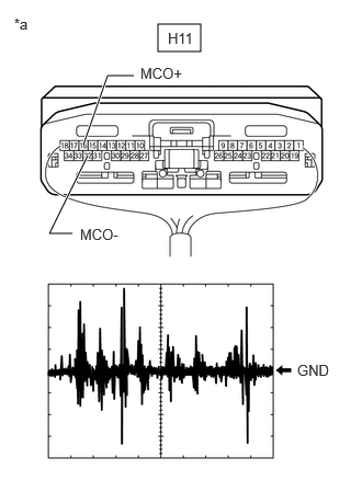
- CHECK TELEPHONE MICROPHONE ASSEMBLY (OUTPUT TO DCM (TELEMATICS TRANSCEIVER))
*a Component with harness connected
(Telephone Microphone Assembly)- Check the output waveform.
- Remove the telephone microphone assembly with the connector(s) still connected.
Refer to REMOVAL [12/2019 - 10/2022]
- Connect an oscilloscope to terminal R12-2 (MCO+) and R12-4 (MCO-).
- Turn the ignition switch to ACC.
- Sound is input to the telephone microphone assembly when the user is closer than 125 mm from the telephone microphone assembly sound holes in the roof headlining holder cover.
- Check the signal waveform according to the condition(s) in the table below.
Item Condition Measurement terminal R12-2 (MCO+) - R12-4 (MCO-) Tool setting 50 mV/DIV., 500 ms/DIV. Vehicle condition - Turn the ignition switch to ACC
- Sound is input to the telephone microphone assembly when the user is closer than 125 mm from the telephone microphone assembly sound holes in the roof headlining holder cover.
OK
The waveform is similar to that shown in the illustration.
HINT:
The oscilloscope waveform shown in the illustration is an example for reference only.
Result
Proceed to OK NG - Remove the telephone microphone assembly with the connector(s) still connected.
Result:
NG
REPLACE TELEPHONE MICROPHONE ASSEMBLY. Refer to REMOVAL [12/2019 - 10/2022]
Result:
OK
See step 14
- Check the output waveform.
- CHECK DCM (TELEMATICS TRANSCEIVER) (OUTPUT TO RADIO AND DISPLAY RECEIVER ASSEMBLY)
*a Component with harness connected
(DCM (Telematics Transceiver))- Check the output waveform.
- Remove the DCM (telematics transceiver) with the connector(s) still connected.
Refer to REMOVAL [12/2019 - 10/2022]
- Connect an oscilloscope to terminal H11-16 (MCO+) and H11-32 (MCO-).
- Turn the ignition switch to ACC.
- Sound is input to the telephone microphone assembly when the user is closer than 125 mm from the telephone microphone assembly sound holes in the roof headlining holder cover.
- Check the signal waveform according to the condition(s) in the table below.
Item Condition Measurement terminal H11-16 (MCO+) - H11-32 (MCO-) Tool setting 50 mV/DIV., 500 ms/DIV. Vehicle condition - Turn the ignition switch to ACC
- Sound is input to the telephone microphone assembly when the user is closer than 125 mm from the telephone microphone assembly sound holes in the roof headlining holder cover.
OK
The waveform is similar to that shown in the illustration.
HINT:
The oscilloscope waveform shown in the illustration is an example for reference only.
Result
Proceed to OK NG - Remove the DCM (telematics transceiver) with the connector(s) still connected.
Result:
OK
REPLACE RADIO AND DISPLAY RECEIVER ASSEMBLY. Refer to REMOVAL [12/2019 - 10/2022]
Result:
NG
REPLACE DCM (TELEMATICS TRANSCEIVER). Refer to REMOVAL [12/2019 - 10/2022]
- Check the output waveform.