DTC U029A-87: Lost Communication with Hybrid/EV Battery Sensor Module Missing Message [12/2019 - 11/2023]: Procedure
- CHECK DTC OUTPUT (HYBRID CONTROL)
- Check and record any Hybrid System DTCs and Freeze Frame Data. Check for DTCs.
Powertrain > Hybrid Control > Trouble Codes
Result
Result Proceed to Only U029A-87 is output. A DTCs other than U029A-87 are also output. B - Turn the ignition switch off.
Result:
B
GO TO DTC CHART (HYBRID CONTROL SYSTEM). Refer to DIAGNOSTIC TROUBLE CODE CHART [12/2019 - 09/2020] , or refer to DIAGNOSTIC TROUBLE CODE CHART [09/2020 - 10/2021] , or refer to DIAGNOSTIC TROUBLE CODE CHART [10/2021 - 11/2023]
Result:
A
See step 2
- Check and record any Hybrid System DTCs and Freeze Frame Data. Check for DTCs.
- CHECK BATTERY VOLTAGE SENSOR (IGCT VOLTAGE) WARNING:
Be sure to wear insulated gloves.
- Check that the service plug grip is not installed.NOTE:
After removing the service plug grip, do not turn the ignition switch to ON (READY), unless instructed by the repair information because this may cause a malfunction.
- Remove the No. 1 hybrid battery shield sub-assembly.
Refer to REMOVAL [12/2019 - 10/2022] , or refer to REMOVAL [10/2022 - 11/2023]
- Connect the cable to the negative (-) auxiliary battery terminal.
- Turn the ignition switch to ON.
- Measure the voltage according to the value(s) in the table below.
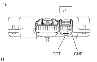
*a Component with harness connected
(Battery Voltage Sensor)Standard Voltage
Tester Connection Condition Specified Condition y1-1 (IGCT) - y1-7 (GND) Ignition switch ON 11 to 14 V NOTE:Turning the ignition switch to ON with the service plug grip removed causes other DTCs to be stored. Clear the DTCs after performing this inspection.
HINT:
As there might be an intermittent malfunction in the battery voltage sensor power source circuit, inspect the following even if the measured voltage is as specified:
- Installation condition of fuse(s) (before removing fuse(s)) (IGCT circuit)
- Fuse condition (before and after removing fuse(s)) (IGCT circuit)
- Connection condition of connectors (IGCT circuit)
- Wire harness condition (IGCT circuit)
- Wire harness condition (GND circuit)
- Turn the ignition switch off.
- Disconnect the cable from the negative (-) auxiliary battery terminal.
- Install the No. 1 hybrid battery shield sub-assembly.
Result
Proceed to OK NG
Result:
NG
REPAIR OR REPLACE HARNESS OR CONNECTOR (BATTERY VOLTAGE SENSOR POWER SOURCE CIRCUIT)
Result:
OK
See step 3
- Check that the service plug grip is not installed.
- CHECK HARNESS AND CONNECTOR (HYBRID VEHICLE CONTROL ECU - BATTERY VOLTAGE SENSOR) WARNING:
Be sure to wear insulated gloves.
- Check that the service plug grip is not installed.NOTE:
After removing the service plug grip, do not turn the ignition switch to ON (READY), unless instructed by the repair information because this may cause a malfunction.
- Disconnect the A32 hybrid vehicle control ECU connector.NOTE:
- Before disconnecting the connector, check that it is not loose or disconnected.
- Check that each connector between the hybrid vehicle control ECU and battery voltage sensor is not loose or disconnected.
- Remove the No. 1 hybrid battery shield sub-assembly.
Refer to REMOVAL [12/2019 - 10/2022] , or refer to REMOVAL [10/2022 - 11/2023]
- Disconnect the y1 battery voltage sensor connector.NOTE:
- Before disconnecting the connector, check that it is not loose or disconnected.
- Check the terminals of the connector for deformation and corrosion.
- Measure the resistance according to the value(s) in the table below.
Standard Resistance
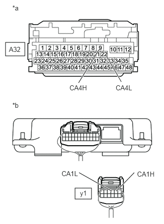
Tester Connection Condition Specified Condition A32-9 (CA4H) - y1-2 (CA1H) Ignition switch off Below 1 Ω A32-22 (CA4L) - y1-3 (CA1L) Ignition switch off Below 1 Ω y1-2 (CA1H) - Body ground and other terminals Ignition switch off 10 kΩ or higher y1-3 (CA1L) - Body ground and other terminals Ignition switch off 10 kΩ or higher *a Front view of wire harness connector
(to Hybrid Vehicle Control ECU)*b Rear view of wire harness connector
(to Battery Voltage Sensor)NOTE:Make sure that each connector between the battery voltage sensor and hybrid vehicle control ECU is not loose or disconnected and its terminals are not deformed or corroded.
- Reconnect the y1 battery voltage sensor connector.
- Install the No. 1 hybrid battery shield sub-assembly.
- Reconnect the A32 hybrid vehicle control ECU connector.
Result
Proceed to OK NG
Result:
OK
REPLACE BATTERY VOLTAGE SENSOR. Refer to REMOVAL [12/2019 - 10/2022] , or refer to REMOVAL [10/2022 - 11/2023]
Result:
NG
REPAIR OR REPLACE HARNESS OR CONNECTOR
- Check that the service plug grip is not installed.