Transmission Control Switch Circuit [12/2019 - 11/2023]: Procedure
- READ VALUE USING GTS (SPORTS SHIFT POSITION)
- Read the Data List using the GTS.
Powertrain > Hybrid Control > Data List
Tester Display Sports Shift Position Result
Result Proceed to GTS display changes according to shift lever operation A GTS display does not change according to shift lever operation B - Turn the ignition switch off.
Result:
B
See step 4
Result:
A
See step 2
- Read the Data List using the GTS.
- READ VALUE USING GTS (SPORTS SHIFT UP SIGNAL, SPORTS SHIFT DOWN SIGNAL)
- Read the Data List using the GTS.
Powertrain > Hybrid Control > Data List
Tester Display Sports Shift UP Signal Sports Shift DOWN Signal Result
Result Proceed to GTS display changes according to transmission control switch operation A GTS display does not change according to transmission control switch operation B - Turn the ignition switch off.
Result:
B
See step 7
Result:
A
See step 3
- Read the Data List using the GTS.
- CHECK FOR INTERMITTENT PROBLEMS
Refer to CHECK FOR INTERMITTENT PROBLEMS [12/2019 - 11/2023]
Result
Proceed to OK NG Result:
OK
REPLACE HYBRID VEHICLE CONTROL ECU. Refer to REMOVAL [12/2019 - 10/2022] , or refer to REMOVAL [10/2022 - 11/2023]
Result:
NG
REPAIR OR REPLACE MALFUNCTIONING PARTS, COMPONENT AND AREA
- CHECK HARNESS AND CONNECTOR (POWER SOURCE CIRCUIT)
- Disconnect the H29 transmission control switch (shift lock control unit assembly) connector.
- Turn the ignition switch to ON.
- Measure the voltage according to the value(s) in the table below.
Standard Voltage
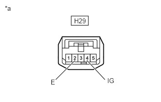
Tester Connection Condition Specified Condition H29-4 (IG) - Body ground Ignition switch ON 11 to 14 V *a Front view of wire harness connector
(to Transmission Control Switch (Shift Lock Control Unit Assembly)) - Turn the ignition switch off.
- Measure the voltage according to the value(s) in the table below.
Standard Voltage
Tester Connection Condition Specified Condition H29-4 (IG) - Body ground Ignition switch off Below 1 V - Measure the resistance according to the value(s) in the table below.
Standard Resistance
Tester Connection Condition Specified Condition H29-2 (E) - Body ground Ignition switch off Below 1 Ω - Reconnect the H29 transmission control switch (shift lock control unit assembly) connector.
Result
Proceed to OK NG
Result:
NG
CHECK POWER SOURCE CIRCUIT
Result:
OK
See step 5
- INSPECT TRANSMISSION CONTROL SWITCH (SHIFT LOCK CONTROL UNIT ASSEMBLY)
Refer to PROCEDURE - Step 2
Result
Proceed to OK NG Result:
NG
REPLACE SHIFT LOCK CONTROL UNIT ASSEMBLY. Refer to REMOVAL [12/2019 - ]
Result:
OK
See step 6
- CHECK HARNESS AND CONNECTOR (HYBRID VEHICLE CONTROL ECU - TRANSMISSION CONTROL SWITCH)
- Disconnect the H67 hybrid vehicle control ECU connector.
- Turn the ignition switch to ON.
- Measure the voltage according to the value(s) in the table below when the shift lever is moved to each position.
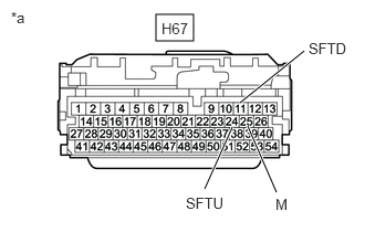
*a Front view of wire harness connector
(to Hybrid Vehicle Control ECU)Standard Voltage
Tester Connection Condition Specified Condition H67-25 (M) - Body ground Ignition switch ON
Shift lever in S, "+" or "-"11 to 14 V Ignition switch ON
Except shift lever in S, "+" and "-"Below 1 V NOTE:If the ignition switch is turned to ON with the hybrid vehicle control ECU connector disconnected, other DTCs will be stored. After performing the inspection, clear the DTCs.
- Turn the ignition switch off.
- Measure the resistance according to the value(s) in the table below when the shift lever is moved to each position.
Standard Resistance
Tester Connection Condition Specified Condition H67-24 (SFTU) - Body ground Shift lever held in "+" Below 1 Ω H67-24 (SFTU) - Body ground Shift lever in S 10 kΩ or higher H67-11 (SFTD) - Body ground Shift lever held in "-" Below 1 Ω H67-11 (SFTD) - Body ground Shift lever in S 10 kΩ or higher - Reconnect the H67 hybrid vehicle control ECU connector.
Result
Proceed to OK NG
Result:
OK
REPLACE HYBRID VEHICLE CONTROL ECU. Refer to REMOVAL [12/2019 - 10/2022] , or refer to REMOVAL [10/2022 - 11/2023]
Result:
NG
REPAIR OR REPLACE HARNESS OR CONNECTOR
- INSPECT TRANSMISSION CONTROL SWITCH (SHIFT LOCK CONTROL UNIT ASSEMBLY)
Refer to PROCEDURE - Step 2
Result
Proceed to OK NG Result:
NG
REPLACE SHIFT LOCK CONTROL UNIT ASSEMBLY. Refer to REMOVAL [12/2019 - ]
Result:
OK
See step 8
- CHECK HARNESS AND CONNECTOR (TRANSMISSION CONTROL SWITCH - HYBRID VEHICLE CONTROL ECU)
- Disconnect the H67 hybrid vehicle control ECU connector.
- Measure the resistance according to the value(s) in the table below when the shift lever is moved to each position.
Standard Resistance
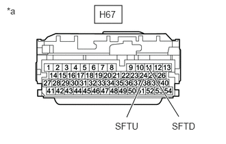
Tester Connection Condition Specified Condition H67-24 (SFTU) - Body ground Shift lever held in "+" Below 1 Ω H67-24 (SFTU) - Body ground Shift lever in S 10 kΩ or higher H67-11 (SFTD) - Body ground Shift lever held in "-" Below 1 Ω H67-11 (SFTD) - Body ground Shift lever in S 10 kΩ or higher *a Front view of wire harness connector
(to Hybrid Vehicle Control ECU) - Reconnect the H67 hybrid vehicle control ECU connector.
Result
Proceed to OK NG
Result:
OK
REPLACE HYBRID VEHICLE CONTROL ECU. Refer to REMOVAL [12/2019 - 10/2022] , or refer to REMOVAL [10/2022 - 11/2023]
Result:
NG
REPAIR OR REPLACE HARNESS OR CONNECTOR