Indicator Circuit [12/2019 - 11/2023]: Procedure
- CHECK SHIFT POSITION INDICATOR
- Turn the ignition switch to ON (ACC).
- Check that each shift position indicator light turns on correctly.
Result
Result Proceed to All shift position indicator lights turn on simultaneously A Shift position indicator lights other than corresponding one turns on B Corresponding shift position indicator light does not turn on C No shift position indicator lights turn on D - Turn the ignition switch off.
Result:
A
See step 2
Result:
C
See step 4
Result:
D
See step 4
Result:
B
See step 2
- CHECK HARNESS AND CONNECTOR (CHECK FOR SHORT TO GROUND)
- Disconnect the H67 hybrid vehicle control ECU connector.
- Measure the resistance according to the value(s) in the table below.
Standard Resistance
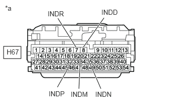
Tester Connection Condition Specified Condition H67-19 (INDP) - Body ground and other terminals Always 10 kΩ or higher H67-7 (INDR) - Body ground and other terminals Always 10 kΩ or higher H67-21 (INDN) - Body ground and other terminals Always 10 kΩ or higher H67-8 (INDD) - Body ground and other terminals Always 10 kΩ or higher H67-20 (INDM) - Body ground and other terminals Always 10 kΩ or higher *a Front view of wire harness connector
(to Hybrid Vehicle Control ECU) - Reconnect the H67 hybrid vehicle control ECU connector.
Result
Proceed to OK NG
Result:
OK
REPLACE HYBRID VEHICLE CONTROL ECU. Refer to REMOVAL [12/2019 - 10/2022] , or refer to REMOVAL [10/2022 - 11/2023]
Result:
NG
See step 3
- CHECK HARNESS AND CONNECTOR (HYBRID VEHICLE CONTROL ECU - SHIFT POSITION INDICATOR)
- Disconnect the H67 hybrid vehicle control ECU connector.
- Disconnect the P1 shift position indicator connector.
- Measure the resistance according to the value(s) in the table below.
Standard Resistance
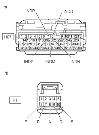
Tester Connection Condition Specified Condition H67-19 (INDP) or P1-6 (P) - Body ground and other terminals Always 10 kΩ or higher H67-7 (INDR) or P1-7 (R) - Body ground and other terminals Always 10 kΩ or higher H67-21 (INDN) or P1-8 (N) - Body ground and other terminals Always 10 kΩ or higher H67-8 (INDD) or P1-9 (D) - Body ground and other terminals Always 10 kΩ or higher H67-20 (INDM) or P1-10 (S) - Body ground and other terminals Always 10 kΩ or higher *a Front view of wire harness connector
(to Hybrid Vehicle Control ECU)*b Front view of wire harness connector
(to Shift Position Indicator) - Reconnect the P1 shift position indicator connector.
- Reconnect the H67 hybrid vehicle control ECU connector.
Result
Proceed to OK NG
Result:
OK
REPLACE SHIFT POSITION INDICATOR. Refer to DISASSEMBLY [12/2019 - ]
Result:
NG
REPAIR OR REPLACE HARNESS OR CONNECTOR
- CHECK HARNESS AND CONNECTOR (POWER SOURCE CIRCUIT)
- Disconnect the P1 shift position indicator connector.
- Turn the ignition switch to ON (ACC).
- Measure the voltage according to the value(s) in the table below.
Standard Voltage
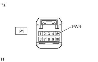
Tester Connection Condition Specified Condition P1-5 (PWR) - Body ground Ignition switch on (ACC) 11 to 14 V *a Front view of wire harness connector
(to Shift Position Indicator) - Turn the ignition switch off.
- Reconnect the P1 shift position indicator connector.
Result
Proceed to OK NG
Result:
NG
REPAIR OR REPLACE POWER SOURCE CIRCUIT
Result:
OK
See step 5
- CHECK HARNESS AND CONNECTOR (POWER SOURCE TERMINAL ACCI)
- Turn the ignition switch to ON (ACC).
- Measure the voltage according to the value(s) in the table below.
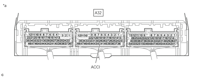
*a Component with harness connected
(Hybrid Vehicle Control ECU)- - Standard Voltage
Tester Connection Condition Specified Condition A32-29 (ACCI) - Body ground Ignition switch ON (ACC) 11 to 14 V - Turn the ignition switch off.
Result
Proceed to OK NG
Result:
NG
REPAIR OR REPLACE POWER SOURCE CIRCUIT
Result:
OK
See step 6
- CHECK HARNESS AND CONNECTOR (CHECK FOR OPEN)
- Disconnect the H67 hybrid vehicle control ECU connector.
- Turn the ignition switch to ON (ACC).
- Measure the voltage according to the value(s) in the table below.
Standard Voltage
Tester Connection Condition Specified Condition H67-19 (INDP) - Body ground and other terminals Ignition switch ON (ACC) 11 to 14 V H67-7 (INDR) - Body ground and other terminals Ignition switch ON (ACC) 11 to 14 V H67-21 (INDN) - Body ground and other terminals Ignition switch ON (ACC) 11 to 14 V H67-8 (INDD) - Body ground and other terminals Ignition switch ON (ACC) 11 to 14 V H67-20 (INDM) - Body ground and other terminals Ignition switch ON (ACC) 11 to 14 V *a Front view of wire harness connector
(to Hybrid Vehicle Control ECU) - Turn the ignition switch off.
- Reconnect the H67 hybrid vehicle control ECU connector.
Result
Proceed to OK NG
Result:
OK
REPLACE HYBRID VEHICLE CONTROL ECU. Refer to REMOVAL [12/2019 - 10/2022] , or refer to REMOVAL [10/2022 - 11/2023]
Result:
NG
See step 7
- CHECK HARNESS AND CONNECTOR (HYBRID VEHICLE CONTROL ECU - SHIFT POSITION INDICATOR)
- Disconnect the H67 hybrid vehicle control ECU connector.
- Disconnect the P1 shift position indicator connector.
- Measure the resistance according to the value(s) in the table below.
Standard Resistance
Tester Connection Condition Specified Condition H67-19 (INDP) - P1-6 (P) Always Below 1 Ω H67-7 (INDR) - P1-7 (R) Always Below 1 Ω H67-21 (INDN) - P1-8 (N) Always Below 1 Ω H67-8 (INDD) - P1-9 (D) Always Below 1 Ω H67-20 (INDM) - P1-10 (S) Always Below 1 Ω *a Front view of wire harness connector
(to Hybrid Vehicle Control ECU)*b Front view of wire harness connector
(to Shift Position Indicator) - Reconnect the P1 shift position indicator connector.
- Reconnect the H67 hybrid vehicle control ECU connector.
Result
Proceed to OK NG
Result:
OK
REPLACE SHIFT POSITION INDICATOR. Refer to DISASSEMBLY [12/2019 - ]
Result:
NG
REPAIR OR REPLACE HARNESS OR CONNECTOR