Inverter Low-voltage Circuit [12/2019 - 11/2023]: Procedure
- CHECK FUSE (PCU)
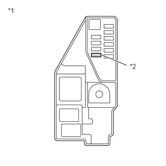
- Remove the PCU fuse from the No. 5 floor relay block and No. 5 floor junction block assembly.
*1 No. 5 Floor Relay Block and No. 5 Floor Junction Block Assembly *2 PCU Fuse - Measure the resistance according to the value(s) in the table below.
Standard Resistance
Tester Connection Condition Specified Condition PCU fuse Always Below 1 Ω - Install the PCU fuse.
Result
Proceed to OK NG
Result:
NG
See step 5
Result:
OK
See step 2
- Remove the PCU fuse from the No. 5 floor relay block and No. 5 floor junction block assembly.
- CHECK HARNESS AND CONNECTOR (INVERTER WITH CONVERTER ASSEMBLY POWER SOURCE CIRCUIT) WARNING:
Be sure to wear insulated gloves.
- Check that the service plug grip is not installed.NOTE:
After removing the service plug grip, do not turn the ignition switch to ON (READY), unless instructed by the repair information because this may cause a malfunction.
- Disconnect the A55 inverter with converter assembly connector.
- Measure the resistance according to the value(s) in the table below.
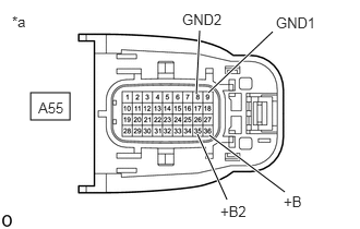
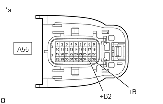
*a Front view of wire harness connector
(to Inverter with Converter Assembly)Standard Resistance
Tester Connection Condition Specified Condition A55-9 (GND1) - Body ground Ignition switch off Below 1 Ω A55-8 (GND2) - Body ground Ignition switch off Below 1 Ω - Connect the cable to the negative (-) auxiliary battery terminal.
- Turn the ignition switch to ON.
- Measure the voltage according to the value(s) in the table below.
Standard Voltage
Tester Connection Condition Specified Condition A55-36 (+B) - Body ground Ignition switch ON Same as auxiliary battery voltage A55-35 (+B2) - Body ground Ignition switch ON Same as auxiliary battery voltage NOTE:Turning the ignition switch to ON with the inverter with converter assembly connector disconnected causes other DTCs to be stored. Clear the DTCs after performing this inspection.
- Turn the ignition switch off.
- Disconnect the cable from the negative (-) auxiliary battery terminal and wait for 2 minutes or more.
- Reconnect the A55 inverter with converter assembly connector.
Result
Proceed to OK NG
Result:
NG
REPAIR OR REPLACE POWER SOURCE CIRCUIT
Result:
OK
See step 3
- Check that the service plug grip is not installed.
- CHECK HARNESS AND CONNECTOR (HYBRID VEHICLE CONTROL ECU - INVERTER WITH CONVERTER ASSEMBLY) WARNING:
Be sure to wear insulated gloves.
- Check that the service plug grip is not installed.NOTE:
After removing the service plug grip, do not turn the ignition switch to ON (READY), unless instructed by the repair information because this may cause a malfunction.
- Disconnect the A55 inverter with converter assembly connector.
- Disconnect the A31 hybrid vehicle control ECU connector.
- Measure the resistance according to the value(s) in the table below.
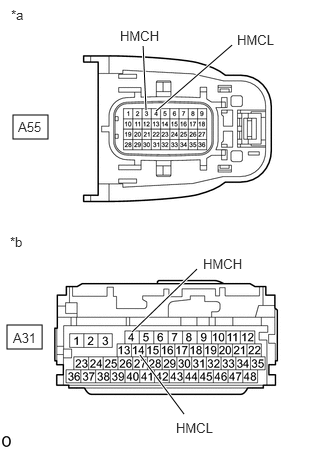
*a Front view of wire harness connector
(to Inverter with Converter Assembly)*b Front view of wire harness connector
(to Hybrid Vehicle Control ECU)Standard Resistance (Check for Open)
Tester Connection Condition Specified Condition A55-3 (HMCH) - A31-4 (HMCH) Ignition switch off Below 1 Ω A55-4 (HMCL) - A31-14 (HMCL) Ignition switch off Below 1 Ω Standard Resistance (Check for Short)
Tester Connection Condition Specified Condition A55-3 (HMCH) or A31-4 (HMCH) - Body ground and other terminals Ignition switch off 10 kΩ or higher A55-4 (HMCL) or A31-14 (HMCL) - Body ground and other terminals Ignition switch off 10 kΩ or higher - Connect the cable to the negative (-) auxiliary battery terminal.
- Turn the ignition switch to ON.
- Measure the voltage according to the value(s) in the table below.
Standard Voltage
Tester Connection Condition Specified Condition A55-3 (HMCH) or A31-4 (HMCH) - Body ground and other terminals Ignition switch ON Below 1 V A55-4 (HMCL) or A31-14 (HMCL) - Body ground and other terminals Ignition switch ON Below 1 V NOTE:Turning the ignition switch to ON with the hybrid vehicle control ECU and inverter with converter assembly connectors disconnected causes other DTCs to be stored. Clear the DTCs after performing this inspection.
- Turn the ignition switch off.
- Disconnect the cable from the negative (-) auxiliary battery terminal and wait for 2 minutes or more.
- Reconnect the A31 hybrid vehicle control ECU connector.
- Reconnect the A55 inverter with converter assembly connector.
Result
Proceed to OK NG
Result:
NG
REPAIR OR REPLACE HARNESS OR CONNECTOR
Result:
OK
See step 4
- Check that the service plug grip is not installed.
- CHECK HYBRID VEHICLE CONTROL ECU
- Disconnect the A31 hybrid vehicle control ECU connector.
- Measure the resistance according to the value(s) in the table below.
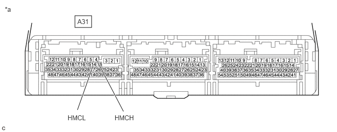
*a Component without harness connected
(Hybrid Vehicle Control ECU)- - Standard Resistance
Tester Connection Condition Specified Condition A31-14 (HMCL) - A31-4 (HMCH) Ignition switch off 80 to 170 Ω - Reconnect the A31 hybrid vehicle control ECU connector.
Result
Proceed to OK NG
Result:
OK
INVERTER LOW-VOLTAGE CIRCUIT NORMAL (PERFORM NEXT STEP FOR REFERENCED DTC)
Result:
NG
REPLACE HYBRID VEHICLE CONTROL ECU. Refer to REMOVAL [12/2019 - 10/2022] , or refer to REMOVAL [10/2022 - 11/2023]
- CHECK HARNESS AND CONNECTOR (INVERTER WITH CONVERTER ASSEMBLY - PCU FUSE) WARNING:
Be sure to wear insulated gloves.
- Check that the service plug grip is not installed.NOTE:
After removing the service plug grip, do not turn the ignition switch to ON (READY), unless instructed by the repair information because this may cause a malfunction.
- Disconnect the A55 inverter with converter assembly connector.
- Measure the resistance according to the value(s) in the table below.
Standard Resistance
Tester Connection Condition Specified Condition A55-36 (+B) - Body ground Ignition switch off 10 kΩ or higher A55-35 (+B2) - Body ground Ignition switch off 10 kΩ or higher *a Front view of wire harness connector
(to Inverter with Converter Assembly) - Reconnect the A55 inverter with converter assembly connector.
Result
Proceed to OK NG
Result:
NG
See step 7
Result:
OK
See step 6
- Check that the service plug grip is not installed.
- REPLACE INVERTER WITH CONVERTER ASSEMBLY
Refer to REMOVAL [12/2019 - 10/2022] , or refer to REMOVAL [10/2022 - 11/2023]
Result
Proceed to NEXT Result:
NEXT
REPLACE FUSE (PCU)
- REPAIR OR REPLACE HARNESS OR CONNECTOR
Result
Proceed to NEXT Result:
NEXT
REPLACE FUSE (PCU)