Cooling Fan Circuit [11/2023 - ]: Procedure
- PERFORM ACTIVE TEST USING GTS (CONTROL THE ENGINE COOLING FAN DUTY RATIO)
- Check the operation of the cooling fan while operating it using the GTS.
Powertrain > Engine > Active Test
Tester Display Control the Engine Cooling Fan Duty Ratio OK
GTS Operation Fan Operation 30 - 100% Cooling fan operates 0% Cooling fan stops Result
Result Proceed to OK A Cooling fan does not operate B Cooling fan does not stop C
Result:
A
PROCEED TO NEXT SUSPECTED AREA SHOWN IN PROBLEM SYMPTOMS TABLE. Refer to PROBLEM SYMPTOMS TABLE [12/2019 - ]
Result:
C
See step 8
Result:
B
See step 2
- Check the operation of the cooling fan while operating it using the GTS.
- CHECK HARNESS AND CONNECTOR (FAN WITH MOTOR ASSEMBLY - ECM)
- Disconnect the A30 fan with motor assembly connector.
- Disconnect the A27 ECM connector.
- Measure the resistance according to the value(s) in the table below.
Standard Resistance
Tester Connection Condition Specified Condition A30-2 (SI) or A27-32 (RFC) - Body ground Always 10 kΩ or higher Result
Proceed to OK NG
Result:
NG
REPAIR OR REPLACE HARNESS OR CONNECTOR (FAN WITH MOTOR ASSEMBLY - ECM)
Result:
OK
See step 3
- INSPECT ECM (RFC TERMINAL)
- Disconnect the A30 fan with motor assembly connector.
- Operate the cooling fan motor (fan with motor assembly) using the Active Test function and measure the resistance according to the value(s) in the table below.
Powertrain > Engine > Active Test
Tester Display Control the Engine Cooling Fan Duty Ratio Standard Resistance
Tester Connection GTS Operation Specified Condition A30-2 (SI) - Body ground Before Active Test (0%) → During Active Test (100%) Before Active Test (0%): Resistance is stable → During Active Test (100%): Resistance fluctuates* HINT:
*: Using the Active Test, duty control of the transistors in the ECM will be performed. Due to the duty control, resistance of the RFC terminal will be unstable during the Active Test. If the resistance is stable before the Active Test and fluctuates while performing the Active Test, it can be determined that the transistor is operating. If the transistor does not operate during the Active Test, the ECM may be malfunctioning.
Result
Proceed to OK NG
Result:
NG
REPLACE ECM. Refer to REMOVAL [11/2023 - ]
Result:
OK
See step 4
- CHECK HARNESS AND CONNECTOR (FAN WITH MOTOR ASSEMBLY POWER SOURCE)
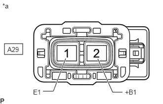
- Disconnect the A29 fan with motor assembly connector.
*a Front view of wire harness connector
(to Fan with Motor Assembly) - Measure the voltage according to the value(s) in the table below.
Standard Voltage
Tester Connection Condition Specified Condition A29-2 (+B1) - A29-1 (E1) Always 11 to 14 V Result
Proceed to OK NG
Result:
NG
See step 7
Result:
OK
See step 5
- Disconnect the A29 fan with motor assembly connector.
- CHECK HARNESS AND CONNECTOR (FAN WITH MOTOR ASSEMBLY POWER SOURCE)
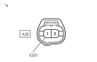
- Disconnect the A30 fan with motor assembly connector.
- Turn the ignition switch to ON.
- Measure the voltage according to the value(s) in the table below.
Standard Voltage
Tester Connection Condition Specified Condition A30-1 (IGS1) - Body ground Ignition switch ON 11 to 14 V *a Front view of wire harness connector
(to Fan with Motor Assembly)Result
Proceed to OK NG
Result:
OK
REPLACE FAN WITH MOTOR ASSEMBLY. Refer to REMOVAL [10/2021 - ]
Result:
NG
See step 6
- CHECK HARNESS AND CONNECTOR (FAN WITH MOTOR ASSEMBLY - EFI-MAIN NO. 1 RELAY)
- Disconnect the A30 fan with motor assembly connector.
- Remove the EFI-MAIN NO. 1 relay from the No. 1 engine room relay block and No. 1 junction block assembly.
- Measure the resistance according to the value(s) in the table below.
Standard Resistance
Tester Connection Condition Specified Condition A30-1 (IGS1) - 5 (EFI-MAIN NO. 1 relay) Always Below 1 Ω Result
Result OK NG
Result:
OK
CHECK ECM POWER SOURCE CIRCUIT. Refer to ECM Power Source Circuit [11/2023 - ]
Result:
NG
REPAIR OR REPLACE HARNESS OR CONNECTOR (FAN WITH MOTOR ASSEMBLY - EFI-MAIN NO. 1 RELAY)
- CHECK HARNESS AND CONNECTOR (FAN WITH MOTOR ASSEMBLY - BODY GROUND)
- Disconnect the A29 fan with motor assembly connector.
- Measure the resistance according to the value(s) in the table below.
Standard Resistance
Tester Connection Condition Specified Condition A29-1 (E1) - Body ground Always Below 1 Ω Result
Proceed to OK NG
Result:
OK
REPAIR OR REPLACE HARNESS OR CONNECTOR (FAN WITH MOTOR ASSEMBLY - BATTERY)
Result:
NG
REPAIR OR REPLACE HARNESS OR CONNECTOR (FAN WITH MOTOR ASSEMBLY - BODY GROUND)
- INSPECT ECM (RFC TERMINAL)
- Disconnect the A30 fan with motor assembly connector.
- Operate the cooling fan motor (fan with motor assembly) using the Active Test function and measure the resistance according to the value(s) in the table below.
Powertrain > Engine > Active Test
Tester Display Control the Engine Cooling Fan Duty Ratio Standard Resistance
Tester Connection GTS Operation Specified Condition A30-2 (SI) - Body ground Before Active Test (0%) → During Active Test (100%) Before Active Test (0%): Resistance is stable → During Active Test (100%): Resistance fluctuates* HINT:
*: Using the Active Test, duty control of the transistors in the ECM will be performed. Due to the duty control, resistance of the RFC terminal will be unstable during the Active Test. If the resistance is stable before the Active Test and fluctuates while performing the Active Test, it can be determined that the transistor is operating. If the transistor does not operate during the Active Test, the ECM may be malfunctioning.
Result
Proceed to OK NG
Result:
OK
REPLACE FAN WITH MOTOR ASSEMBLY. Refer to REMOVAL [10/2021 - ]
Result:
NG
See step 9
- CHECK HARNESS AND CONNECTOR (FAN WITH MOTOR ASSEMBLY - ECM)
- Disconnect the A30 fan with motor assembly connector.
- Disconnect the A27 ECM connector.
- Measure the resistance according to the value(s) in the table below.
Standard Resistance
Tester Connection Condition Specified Condition A30-2 (SI) - A27-32 (RFC) Always Below 1 Ω Result
Result OK NG
Result:
OK
REPLACE ECM. Refer to REMOVAL [11/2023 - ]
Result:
NG
REPAIR OR REPLACE HARNESS OR CONNECTOR (FAN WITH MOTOR ASSEMBLY - ECM)