Inspection [12/2019 - ]: Procedure
WARNING: This page is about a different variant/trim than selected.
- INSPECT EV DRIVE MODE SWITCH (PATTERN SELECT SWITCH ASSEMBLY)
- Check the resistance.
- Measure the resistance according to the value(s) in the table below.
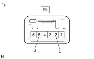
*a Component without harness connected
(EV Drive Mode Switch (Pattern Select Switch Assembly))Standard Resistance
Tester Connection Condition Specified Condition P9-5 (S) - P9-2 (E) EV drive mode switch (pattern select switch assembly) being pushed and held Below 50 Ω EV drive mode switch (pattern select switch assembly) not pushed 10 kΩ or higher If the result is not as specified, replace the EV drive mode switch (pattern select switch assembly).
- Measure the resistance according to the value(s) in the table below.
- Check illumination.
- Apply auxiliary battery voltage between the terminals of the switch, and check the illumination condition of the EV drive mode switch (pattern select switch assembly).
OK
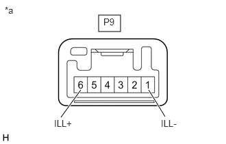
Condition Specified Condition Battery positive (+) → P9-6 (ILL+)
Battery negative (-) →P9-1 (ILL-)Illuminates *a Component without harness connected
(EV Drive Mode Switch (Pattern Select Switch Assembly))If the result is not as specified, replace the EV drive mode switch (pattern select switch assembly).
- Apply auxiliary battery voltage between the terminals of the switch, and check the illumination condition of the EV drive mode switch (pattern select switch assembly).
- Check the resistance.
- INSPECT TRAIL SWITCH (PATTERN SELECT SWITCH)
- Check the resistance.
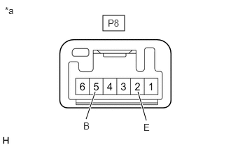
*a Component without harness connected
(Trail Switch (Pattern Select Switch))Measure the resistance according to the value(s) in the table below.
Standard Resistance
Tester Connection Condition Specified Condition P8-5 (B) - P8-2 (E) Trail switch (pattern select switch) being pushed and held Below 1 Ω Trail switch (pattern select switch) not pushed 10 kΩ or higher If the result is not as specified, replace the trail switch (pattern select switch).
- Check illumination.
- Apply auxiliary battery voltage between the terminals of the switch, and check the illumination condition of the trail switch (pattern select switch).
OK
Condition Specified Condition Battery positive (+) → P8-6 (ILL+)
Battery negative (-) →P8-1 (ILL-)Illuminates *a Component without harness connected
(Trail Switch (Pattern Select Switch))If the result is not as specified, replace the trail switch (pattern select switch).
- Apply auxiliary battery voltage between the terminals of the switch, and check the illumination condition of the trail switch (pattern select switch).
- Check the resistance.
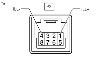
- INSPECT DRIVE MODE SELECT SWITCH (NO. 1 PATTERN SELECT SWITCH ASSEMBLY)
- Check the resistance.
- Measure the resistance according to the value(s) in the table below.
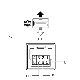
*a Component without harness connected
(Drive Mode Select Switch (No. 1 Pattern Select Switch Assembly))
"DRIVE +" Side 
"DRIVE -" Side Standard Resistance
Tester Connection Condition Specified Condition P3-7 (SEL) - P3-5 (E) Pushed and held at "DRIVE +" side Below 50 Ω Released (neutral position) 10 kΩ or higher P3-6 (E) - P3-5 (E) Pushed and held at "DRIVE -" side Below 50 Ω Released (neutral position) 10 kΩ or higher If the result is not as specified, replace the drive mode select switch (No. 1 pattern select switch assembly).
- Measure the resistance according to the value(s) in the table below.
- Check illumination.
- Apply auxiliary battery voltage between the terminals of the switch, and check the illumination condition of the drive mode select switch (No. 1 pattern select switch assembly).
*a Component without harness connected
(Drive Mode Select Switch (No. 1 Pattern Select Switch Assembly))OK
Condition Specified Condition Auxiliary battery positive (+) → P3-1 (ILL+)
Auxiliary battery negative (-) → P3-4 (ILL-)Illuminates If the result is not as specified, replace the drive mode select switch (No. 1 pattern select switch assembly).
- Apply auxiliary battery voltage between the terminals of the switch, and check the illumination condition of the drive mode select switch (No. 1 pattern select switch assembly).
- Check the resistance.