DTC P0AE4-15: Hybrid/EV Battery Precharge Contactor Circuit Short to Auxiliary Battery or Open [12/2019 - 11/2023]: Procedure
- READ VALUE USING GTS (SMRP STATUS)
- Read the Data List.
Powertrain > Hybrid Control > Data List
Tester Display SMRP Status Standard
Tester Display Condition Specified Condition SMRP Status Ignition switch ON OFF - Turn the ignition switch off.
Result
Proceed to OK NG
Result:
NG
See step 5
Result:
OK
See step 2
- Read the Data List.
- CHECK CONNECTOR CONNECTION CONDITION (HYBRID VEHICLE CONTROL ECU CONNECTOR)
Refer to PROCEDURE - Step 1
Result
Proceed to OK NG Result:
NG
CONNECT SECURELY
Result:
OK
See step 3
- CHECK CONNECTOR CONNECTION CONDITION (FLOOR WIRE CONNECTOR)
Refer to PROCEDURE - Step 5
Result
Result Proceed to OK A NG (The connector is not connected securely.) B NG (The terminals are not making secure contact or are deformed, or water or foreign matter exists in the connector.) C Result:
B
CONNECT SECURELY
Result:
C
REPAIR OR REPLACE HARNESS OR CONNECTOR
Result:
A
See step 4
- CHECK CONNECTOR CONNECTION CONDITION (HV BATTERY JUNCTION BLOCK ASSEMBLY CONNECTOR)
Refer to PROCEDURE - Step 8
Result
Proceed to OK NG Result:
OK
CHECK FOR INTERMITTENT PROBLEMS
Refer to CHECK FOR INTERMITTENT PROBLEMS [12/2019 - 11/2023]
Result:
NG
CONNECT SECURELY
- CHECK HARNESS AND CONNECTOR (SMRP VOLTAGE)
- Turn the ignition switch to ON.
- Measure the voltage according to the value(s) in the table below.
*a Component with harness connected
(Hybrid Vehicle Control ECU)- - Standard Voltage
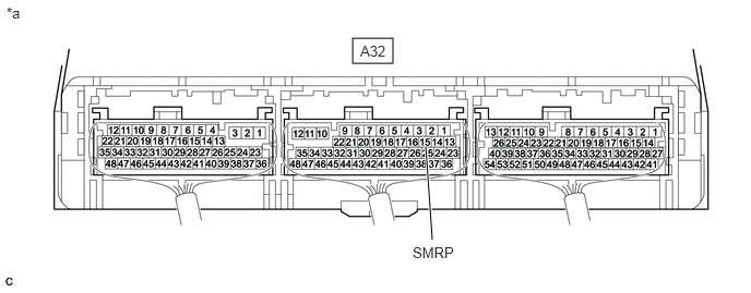
Tester Connection Condition Specified Condition A32-15 (SMRP) - Body ground Ignition switch ON Below 1 V - Turn the ignition switch off.
Result
Proceed to OK NG
Result:
NG
See step 7
Result:
OK
See step 6
- CHECK CONNECTOR CONNECTION CONDITION (HYBRID VEHICLE CONTROL ECU CONNECTOR)
Refer to PROCEDURE - Step 1
Result
Proceed to OK NG Result:
OK
REPLACE HYBRID VEHICLE CONTROL ECU
Refer to REMOVAL [12/2019 - 10/2022] , or refer to REMOVAL [10/2022 - 11/2023]
Result:
NG
CONNECT SECURELY
- CHECK HARNESS AND CONNECTOR (HYBRID VEHICLE CONTROL ECU - BODY GROUND)
- Disconnect the A32 hybrid vehicle control ECU connector.
- Measure the resistance according to the value(s) in the table below.
Standard Resistance
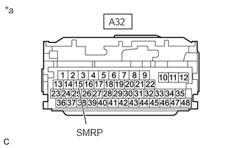
Tester Connection Condition Specified Condition A32-15 (SMRP) - Body ground Ignition switch off 140 to 290 Ω *a Front view of wire harness connector
(to Hybrid Vehicle Control ECU) - Reconnect the A32 hybrid vehicle control ECU connector.
Result
Proceed to OK NG
Result:
NG
See step 9
Result:
OK
See step 8
- CHECK HARNESS AND CONNECTOR (SHORT TO POWER SUPPLY WIRES) WARNING:
Be sure to wear insulated gloves.
- Check that the service plug grip is not installed.NOTE:
After removing the service plug grip, do not turn the ignition switch to ON (READY), unless instructed by the repair information because this may cause a malfunction.
- Remove the No. 10 HV battery shield panel.
Refer to REMOVAL [12/2019 - 10/2022] , or refer to REMOVAL [10/2022 - 11/2023]
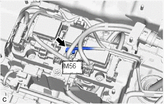
- Disconnect the M56 HV battery junction block assembly connector.
- Disconnect the A32 hybrid vehicle control ECU connector.
- Turn the ignition switch to ON.
- Measure the voltage according to the value(s) in the table below.
Standard Voltage
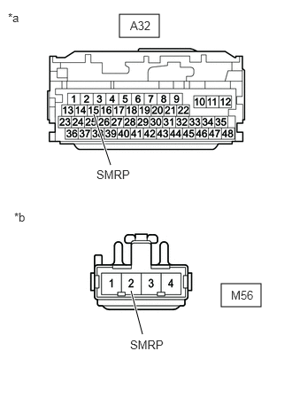
Tester Connection Condition Specified Condition A32-15 (SMRP) or M56-2 (SMRP) - Body ground Ignition switch ON Below 1 V NOTE:Turning the ignition switch to ON with the hybrid vehicle control ECU connector and the HV battery junction block assembly connector disconnected causes other DTCs to be stored. Clear the DTCs after performing this inspection.
*a Front view of wire harness connector
(to Hybrid Vehicle Control ECU)*b Front view of wire harness connector
(to HV Battery Junction Block Assembly) - Turn the ignition switch off.
- Reconnect the A32 hybrid vehicle control ECU connector.
- Reconnect the M56 HV battery junction block assembly connector.
- Install the No. 10 HV battery shield panel.
Result
Proceed to OK NG
Result:
OK
REPLACE HYBRID VEHICLE CONTROL ECU
Refer to REMOVAL [12/2019 - 10/2022] , or refer to REMOVAL [10/2022 - 11/2023]
Result:
NG
REPAIR OR REPLACE HARNESS OR CONNECTOR
- Check that the service plug grip is not installed.
- CHECK CONNECTOR CONNECTION CONDITION (FLOOR WIRE CONNECTOR)
Refer to PROCEDURE - Step 5
Result
Result Proceed to OK A NG (The connector is not connected securely.) B NG (The terminals are not making secure contact or are deformed, or water or foreign matter exists in the connector.) C Result:
B
CONNECT SECURELY
Result:
C
REPAIR OR REPLACE HARNESS OR CONNECTOR
Result:
A
See step 10
- CHECK HARNESS AND CONNECTOR (HYBRID VEHICLE CONTROL ECU - HV BATTERY JUNCTION BLOCK ASSEMBLY) WARNING:
Be sure to wear insulated gloves.
- Check that the service plug grip is not installed.NOTE:
After removing the service plug grip, do not turn the ignition switch to ON (READY), unless instructed by the repair information because this may cause a malfunction.
- Remove the No. 10 HV battery shield panel.
Refer to REMOVAL [12/2019 - 10/2022] , or refer to REMOVAL [10/2022 - 11/2023]
- Disconnect the M56 HV battery junction block assembly connector.
- Disconnect the A32 hybrid vehicle control ECU connector.
- Measure the resistance according to the value(s) in the table below.
Standard Resistance (Check for Open)
Tester Connection Condition Specified Condition A32-15 (SMRP) - M56-2 (SMRP) Ignition switch off Below 1 Ω Standard Resistance (Check for Short)
Tester Connection Condition Specified Condition A32-15 (SMRP) or M56-2 (SMRP) - Body ground and other terminals Ignition switch off 10 kΩ or higher *a Front view of wire harness connector
(to Hybrid Vehicle Control ECU)*b Front view of wire harness connector
(to HV Battery Junction Block Assembly) - Reconnect the A32 hybrid vehicle control ECU connector.
- Reconnect the M56 HV battery junction block assembly connector.
- Install the No. 10 HV battery shield panel.
Result
Proceed to OK NG
Result:
NG
REPAIR OR REPLACE HARNESS OR CONNECTOR
Result:
OK
See step 11
- Check that the service plug grip is not installed.
- CHECK HARNESS AND CONNECTOR (HV BATTERY JUNCTION BLOCK ASSEMBLY - BODY GROUND)
See step 11
Result
Proceed to OK NG Result:
NG
REPAIR OR REPLACE HARNESS OR CONNECTOR
Result:
OK
See step 12
- INSPECT HV BATTERY JUNCTION BLOCK ASSEMBLY (SMRP) WARNING:
Be sure to wear insulated gloves.
- Check that the service plug grip is not installed.NOTE:
After removing the service plug grip, do not turn the ignition switch to ON (READY), unless instructed by the repair information because this may cause a malfunction.
- Remove the No. 10 HV battery shield panel.
Refer to REMOVAL [12/2019 - 10/2022] , or refer to REMOVAL [10/2022 - 11/2023]
- Disconnect the M56 HV battery junction block assembly connector.
- Measure the resistance according to the value(s) in the table below.
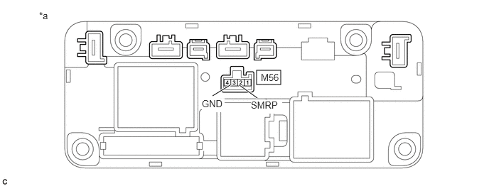
*a Component without harness connected
(HV Battery Junction Block Assembly)- - Standard Resistance
Tester Connection Condition Specified Condition M56-2 (SMRP) - M56-3 (GND) -40 to 80°C (-40 to 176°F) 140 to 290 Ω - Reconnect the M56 HV battery junction block assembly connector.
- Install the No. 10 HV battery shield panel.
Result
Proceed to OK NG
Result:
OK
CHECK FOR INTERMITTENT PROBLEMS
Refer to CHECK FOR INTERMITTENT PROBLEMS [12/2019 - 11/2023]
Result:
NG
REPLACE HV BATTERY JUNCTION BLOCK ASSEMBLY
Refer to REMOVAL [12/2019 - 10/2022] , or refer to REMOVAL [10/2022 - 11/2023]
- Check that the service plug grip is not installed.