DTC P0AFC-00: Hybrid/EV Battery Sensor Module; DTC P0AFC-16: Hybrid/EV Battery Sensor Module Circuit Voltage Below Threshold; DTC P0AFC-96: Hybrid/EV Battery Sensor Module Component Internal Failure; DTC P308A-12: Hybrid/EV Battery Voltage Sensor All Circuit Short to Auxiliary Battery [12/2019 - 11/2023]: Procedure
- CHECK CONNECTOR CONNECTION CONDITION (BATTERY VOLTAGE SENSOR CONNECTOR) WARNING:
Be sure to wear insulated gloves.
- Check that the service plug grip is not installed.NOTE:
After removing the service plug grip, do not turn the ignition switch to ON (READY), unless instructed by the repair information because this may cause a malfunction.
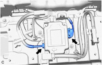
- Remove the HV battery junction block assembly.
Refer to REMOVAL [12/2019 - 10/2022] , or refer to REMOVAL [10/2022 - 11/2023]
- Check the connector connections and contact pressure of the relevant terminals of the battery voltage sensor connectors.
Refer to ELECTRONIC CIRCUIT INSPECTION PROCEDURE [12/2019 - ]
OK
The connectors are connected securely and there are no contact pressure problems.
Result
Proceed to OK NG - Install the HV battery junction block assembly.
Result:
NG
CONNECT SECURELY
Result:
OK
See step 2
- Check that the service plug grip is not installed.
- CHECK HARNESS AND CONNECTOR (IGCT VOLTAGE) WARNING:
Be sure to wear insulated gloves.
- Check that the service plug grip is not installed.NOTE:
- Check and record any DTCs, INF codes and freeze frame data, then disconnect the cable from the negative (-) auxiliary battery terminal.
- After removing the service plug grip, do not turn the ignition switch to ON (READY), unless instructed by the repair information because this may cause a malfunction.
- Remove the HV battery junction block assembly.
Refer to REMOVAL [12/2019 - 10/2022] , or refer to REMOVAL [10/2022 - 11/2023]
- Connect the cable to the negative (-) auxiliary battery terminal.
- Turn the ignition switch to ON.
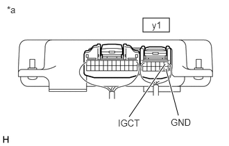
- Measure the voltage according to the value(s) in the table below.
*a Component with harness connected
(Battery Voltage Sensor)Standard Voltage
Tester Connection Condition Specified Condition y1-1 (IGCT) - y1-7 (GND) Ignition switch ON 11 to 14 V NOTE:Turning the ignition switch to ON with the service plug grip removed causes other DTCs to be stored. Clear the DTCs after performing this inspection.
- Turn the ignition switch off.
- Disconnect the cable from the negative (-) auxiliary battery terminal.
- Install the HV battery junction block assembly.
Result
Proceed to OK NG
Result:
OK
REPLACE BATTERY VOLTAGE SENSOR. Refer to REMOVAL [12/2019 - 10/2022] , or refer to REMOVAL [10/2022 - 11/2023]
Result:
NG
See step 3
- Check that the service plug grip is not installed.
- CHECK HARNESS AND CONNECTOR (BATTERY VOLTAGE SENSOR - BODY GROUND) WARNING:
Be sure to wear insulated gloves.
- Check that the service plug grip is not installed.NOTE:
After removing the service plug grip, do not turn the ignition switch to ON (READY), unless instructed by the repair information because this may cause a malfunction.
- Remove the HV battery junction block assembly.
Refer to REMOVAL [12/2019 - 10/2022] , or refer to REMOVAL [10/2022 - 11/2023]
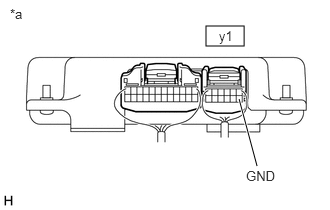
- Measure the resistance according to the value(s) in the table below.
Standard Resistance
Tester Connection Condition Specified Condition y1-7 (GND) - Body ground Ignition switch off Below 1 Ω *a Component with harness connected
(Battery Voltage Sensor) - Install the HV battery junction block assembly.
Result
Proceed to OK NG
Result:
OK
REPAIR OR REPLACE HARNESS OR CONNECTOR (IGCT NO. 2 FUSE - BATTERY VOLTAGE SENSOR)
Result:
NG
REPAIR OR REPLACE HARNESS OR CONNECTOR (BATTERY VOLTAGE SENSOR - BODY GROUND)
- Check that the service plug grip is not installed.