DTC P0B3B-14: Hybrid/EV Battery Voltage Sensor "A" Circuit Short to Ground or Open; DTC P0B40-14: Hybrid/EV Battery Voltage Sensor "B" Circuit Short to Ground or Open; DTC P0B45-14: Hybrid/EV Battery Voltage Sensor "C" Circuit Short to Ground or Open; DTC P0B4A-14: Hybrid/EV Battery Voltage Sensor "D" Circuit Short to Ground or Open; DTC P0B4F-14: Hybrid/EV Battery Voltage Sensor "E" Circuit Short to Ground or Open; DTC P0B54-14: Hybrid/EV Battery Voltage Sensor "F" Circuit Short to Ground or Open; DTC P0B59-14: Hybrid/EV Battery Voltage Sensor "G" Circuit Short to Ground or Open; DTC P0B5E-14: Hybrid/EV Battery Voltage Sensor "H" Circuit Short to Ground or Open; DTC P0B63-14: Hybrid/EV Battery Voltage Sensor "I" Circuit Short to Ground or Open; DTC P0B68-14: Hybrid/EV Battery Voltage Sensor "J" Circuit Short to Ground or Open; DTC P0B6D-14: Hybrid/EV Battery Voltage Sensor "K" Circuit Short to Ground or Open; DTC P0B72-14: Hybrid/EV Battery Voltage Sensor "L" Circuit Short to Ground or Open; DTC P0B77-14: Hybrid/EV Battery Voltage Sensor "M" Circuit Short to Ground or Open; DTC P308A-13: Hybrid/EV Battery Voltage Sensor All Circuit Open [12/2019 - 11/2023]: Procedure
- CHECK DTC OUTPUT (HYBRID CONTROL)
- Check and record any HV system DTCs and Freeze Frame Data.
Powertrain > Hybrid Control > Trouble Codes
Result
Result Proceed to P0A95-63, P0AFC-00, P0AFC-96 or P308A-12 is not output. A P0A95-63, P0AFC-00, P0AFC-96 or P308A-12 is also output. B - Turn the ignition switch off.
Result:
B
GO TO DTC CHART (HYBRID CONTROL SYSTEM)
Refer to DIAGNOSTIC TROUBLE CODE CHART [12/2019 - 09/2020] , or refer to DIAGNOSTIC TROUBLE CODE CHART [09/2020 - 10/2021] , or refer to DIAGNOSTIC TROUBLE CODE CHART [10/2021 - 11/2023]
Result:
A
See step 2
- Check and record any HV system DTCs and Freeze Frame Data.
- CHECK CONNECTOR CONNECTION CONDITION (BATTERY VOLTAGE SENSOR CONNECTOR)
See step 1
Result
Proceed to OK NG Result:
NG
CONNECT SECURELY
Result:
OK
See step 3
- CHECK DTC OUTPUT (HYBRID CONTROL)
- Check for DTCs.
Powertrain > Hybrid Control > Trouble Codes
HINT:
Check the DTCs that were output when the vehicle was brought to the workshop.
Result
Result Proceed to DTCs other than P308A-13 are also output. A P308A-13 is output B - Turn the ignition switch off.
Result:
B
See step 5
Result:
A
See step 4
- Check for DTCs.
- CHECK BATTERY VOLTAGE SENSOR (BLOCK VOLTAGES) WARNING:
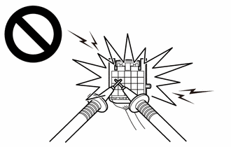
Be sure to wear insulated gloves.
- Check that the service plug grip is not installed.NOTE:
After removing the service plug grip, do not turn the ignition switch to ON (READY), unless instructed by the repair information because this may cause a malfunction.
- Disconnect the high voltage cable connector of the HV battery from the HV battery junction block assembly.NOTE:
Insulate each disconnected high-voltage connector with insulating tape. Wrap the connector from the wire harness side to the end of the connector.
- Disconnect the z15 battery voltage sensor connector.
- Measure the voltage according to the value(s) in the table below.
HINT:
For each output DTC, apply the judgment method in the table below and calculate the voltage value.
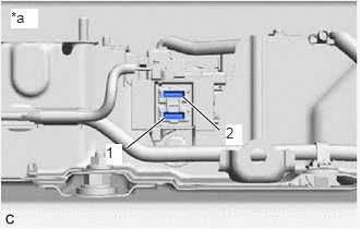
*a Service Plug Grip Removed
(Service Plug Grip Connecting Terminals)Standard Voltage
DTC No. Judgment Method Specified Condition P0B77-14 [A] = [C] 288 to 336 V P0B72-14 [D] 14.4 to 16.8 V P0B6D-14 [E] - [D] 14.4 to 16.8 V P0B68-14 [F] - [E] 28.8 to 33.6 V P0B63-14 [G] - [F] 28.8 to 33.6 V P0B5E-14 [H] - [G] 28.8 to 33.6 V P0B59-14 [I] - [J] 28.8 to 33.6 V P0B54-14 [J] - [K] 28.8 to 33.6 V P0B4F-14 [K] - [L] 28.8 to 33.6 V P0B4A-14 [L] - [M] 28.8 to 33.6 V P0B45-14 [M] - [N] 14.4 to 16.8 V P0B40-14 [N] 14.4 to 16.8 V P0B3B-14 [A] = [B] 288 to 336 V Tester Connection Condition Specified Condition z11-1 (+) (+) - Service plug grip connecting terminals 1 (-) Ignition switch off [A] z11-1 (+) (+) - z15-22 (GB0) (-) Ignition switch off [B] z15-12 (VB20) (+) - Service plug grip connecting terminals 1 (-) Ignition switch off [C] z11-1 (+) (+) - z15-2 (VB19) (-) Ignition switch off [D] z11-1 (+) (+) - z15-13 (VB18) (-) Ignition switch off [E] z11-1 (+) (+) - z15-14 (VB16) (-) Ignition switch off [F] z11-1 (+) (+) - z15-15 (VB14) (-) Ignition switch off [G] z11-1 (+) (+) - z15-16 (VB12) (-) Ignition switch off [H] z15-17 (VB10) (+) - Service plug grip connecting terminals 1 (-) Ignition switch off [I] z15-18 (VB8) (+) - Service plug grip connecting terminals 1 (-) Ignition switch off [J] z15-19 (VB6) (+) - Service plug grip connecting terminals 1 (-) Ignition switch off [K] z15-20 (VB4) (+) - Service plug grip connecting terminals 1 (-) Ignition switch off [L] z15-21 (VB2) (+) - Service plug grip connecting terminals 1 (-) Ignition switch off [M] z15-11 (VB1) (+) - Service plug grip connecting terminals 1 (-) Ignition switch off [N] NOTE:Make sure to check the polarity of each terminal (positive (+) or negative (-)) before connecting a tester.
Result
Proceed to OK NG - Disconnect the z15 battery voltage sensor connector.
- Reconnect the HV battery high voltage cable connectors.
Result:
OK
REPLACE BATTERY VOLTAGE SENSOR
Refer to REMOVAL [12/2019 - 10/2022] , or refer to REMOVAL [10/2022 - 11/2023]
Result:
NG
REPLACE HV BATTERY
Refer to REMOVAL [12/2019 - 10/2022] , or refer to REMOVAL [10/2022 - 11/2023]
- Check that the service plug grip is not installed.
- CHECK BATTERY VOLTAGE SENSOR (BLOCK VOLTAGES) WARNING:
Be sure to wear insulated gloves.
- Check that the service plug grip is not installed.NOTE:
After removing the service plug grip, do not turn the ignition switch to ON (READY), unless instructed by the repair information because this may cause a malfunction.
- Disconnect the high voltage cable connector of the HV battery from the HV battery junction block assembly.NOTE:
Insulate each disconnected high-voltage connector with insulating tape. Wrap the connector from the wire harness side to the end of the connector.
- Disconnect the z15 battery voltage sensor connector.
- Measure the voltage according to the value(s) in the table below.
HINT:
Apply the judgment method in the table below and calculate the voltage value.
*a Service Plug Grip Removed
(Service Plug Grip Connecting Terminals)Standard Voltage
DTC No. Judgment Method Specified Condition P308A-13 [C] - [D] 28.8 to 33.6 V [D] - [E] 14.4 to 16.8 V [E] 14.4 to 16.8 V [A] = [B] 288 to 336 V Tester Connection Condition Specified Condition z11-1 (+) (+) - Service plug grip connecting terminals 1 (-) Ignition switch off [A] z11-1 (+) (+) - z15-22 (GB0) (-) Ignition switch off [B] z15-20 (VB4) (+) - Service plug grip connecting terminals 1 (-) Ignition switch off [C] z15-21 (VB2) (+) - Service plug grip connecting terminals 1 (-) Ignition switch off [D] z15-11 (VB1) (+) - Service plug grip connecting terminals 1 (-) Ignition switch off [E] NOTE:Make sure to check the polarity of each terminal (positive (+) or negative (-)) before connecting a tester.
Result
Proceed to OK NG - Disconnect the z15 battery voltage sensor connector.
- Reconnect the HV battery high voltage cable connectors.
Result:
OK
REPLACE BATTERY VOLTAGE SENSOR
Refer to REMOVAL [12/2019 - 10/2022] , or refer to REMOVAL [10/2022 - 11/2023]
Result:
NG
REPLACE HV BATTERY
Refer to REMOVAL [12/2019 - 10/2022] , or refer to REMOVAL [10/2022 - 11/2023]
- Check that the service plug grip is not installed.