DTC P0C73-96: Motor Electronics Coolant Pump "A" Component Internal Failure [12/2019 - 11/2023]: Procedure
- CHECK DTC OUTPUT (HYBRID CONTROL)
- Check for DTCs.
Powertrain > Hybrid Control > Trouble Codes
Result
Result Proceed to P0C73-96 only is output, or DTCs except the ones in the table below are also output. A Any of the following DTCs including pending DTCs are also output. B Malfunction Content Relevant DTC Microcomputer malfunction P0606-47 Hybrid/EV Powertrain Control Module Processor Watchdog / Safety MCU Failure P0688-1F ECM/PCM Power Relay Sense Circuit Intermittent Sensor and actuator circuit malfunction P314A-31 Motor Electronics Coolant Pump "A" No Signal HINT:
P0C73-96 may be output as a result of the malfunction indicated by the DTCs above.
- The chart above is listed in inspection order of priority.
- Check DTCs that are output at the same time by following the listed order. (The main cause of the malfunction can be determined without performing unnecessary inspections.)
- Turn the ignition switch off.
Result:
B
GO TO DTC CHART (HYBRID CONTROL SYSTEM). Refer to DIAGNOSTIC TROUBLE CODE CHART [12/2019 - 09/2020] , or refer to DIAGNOSTIC TROUBLE CODE CHART [09/2020 - 10/2021] , or refer to DIAGNOSTIC TROUBLE CODE CHART [10/2021 - 11/2023]
Result:
A
See step 2
- Check for DTCs.
- READ VALUE USING GTS (INVERTER WATER PUMP REVOLUTION) NOTE:
Be sure to perform the inspection with the auxiliary battery voltage at 12 V or more.
HINT:
- When the auxiliary battery voltage is low, the inverter water pump assembly may not operate.
- When the inverter water pump assembly signal line (SWP - IWP) is open or its connection is faulty, the inverter water pump assembly is operated forcibly.
- According to the display on the GTS, read the Data List.
Powertrain > Hybrid Control > Data List
Tester Display Inverter Water Pump Revolution OK
Tester Display Condition Specified Condition Inverter Water Pump Revolution Ignition switch ON 200 rpm or less HINT:
When the inverter water pump assembly is not operating, the Data List item "Inverter Water Pump Revolution" displays a value 200 rpm or less.
- Turn the ignition switch off.
Result
Proceed to OK NG
Result:
NG
See step 6
Result:
OK
See step 3
- CLEAR DTC
- Read and record the DTCs and Freeze Frame Data.
Powertrain > Hybrid Control > Trouble Codes
- Clear the DTCs and Freeze Frame Data.
Powertrain > Hybrid Control > Clear DTCs
- Turn the ignition switch off and wait for 2 minutes or more.
Result
Proceed to NEXT
Result:
NEXT
See step 4
- Read and record the DTCs and Freeze Frame Data.
- PERFORM ACTIVE TEST USING GTS (ACTIVATE THE INVERTER WATER PUMP) NOTE:
- Make sure that the HV coolant level is above the low line of the inverter reserve tank.
- Be sure to perform the inspection with the auxiliary battery voltage at 12 V or more.
HINT:
When the auxiliary battery voltage is low, the inverter water pump assembly may not operate.
- According to the display on the GTS, perform the Active Test "Activate the Inverter Water Pump" and, check the value of the Data List item "Inverter Water Pump Revolution".
Powertrain > Hybrid Control > Active Test
Active Test Display Activate the Inverter Water Pump Data List Display Inverter Water Pump Revolution OK
Tester Display Condition Specified Condition Inverter Water Pump Revolution Ignition switch ON
During Active Test3176 to 8617 rpm HINT:
- Perform the Active Test with the inverter coolant temperature between -15 and 65°C (5 to 149°F).
- When the inverter water pump assembly is not operating, the Data List item "Inverter Water Pump Revolution" displays a value 200 rpm or less.
- Turn the ignition switch off.
Result
Proceed to OK NG
Result:
NG
See step 6
Result:
OK
See step 5
- CHECK HV COOLANT (CHECK FOR CONDITIONS THAT MAY HAVE CAUSED FREEZING)
Refer to PROCEDURE - Step 8 [12/2019 - 10/2021] , or refer to PROCEDURE - Step 8 [10/2021 - 11/2023]
Result
Result Proceed to Ambient Temperature value is above freezing temperature of the HV coolant. A Ambient Temperature value is below freezing temperature of the HV coolant. B Result:
A
See step 12
Result:
B
REPLACE HV COOLANT. Refer to REPLACEMENT [12/2019 - ]
- CHECK CONNECTOR CONNECTION CONDITION (HYBRID VEHICLE CONTROL ECU CONNECTOR)
Refer to PROCEDURE - Step 1
Result
Proceed to OK NG Result:
NG
CONNECT SECURELY
Result:
OK
See step 7
- CHECK CONNECTOR CONNECTION CONDITION (INVERTER WATER PUMP ASSEMBLY CONNECTOR)
Refer to PROCEDURE - Step 10 [12/2019 - 10/2021] , or refer to PROCEDURE - Step 10 [10/2021 - 11/2023]
Result
Proceed to OK NG Result:
NG
CONNECT SECURELY
Result:
OK
See step 8
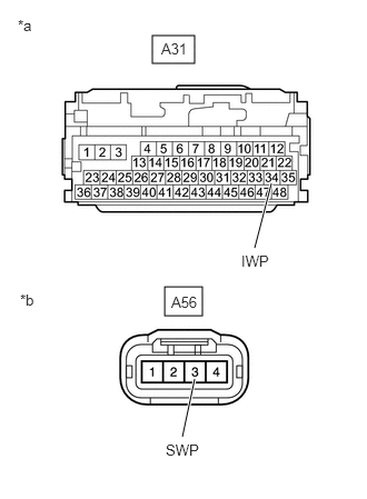
- CHECK HARNESS AND CONNECTOR (HYBRID VEHICLE CONTROL ECU - INVERTER WATER PUMP ASSEMBLY)
- Disconnect the A31 hybrid vehicle control ECU connector.
- Disconnect the A56 inverter water pump assembly connector.
- Measure the resistance according to the value(s) in the table below.
Standard Resistance (Check for Open)
Tester Connection Condition Specified Condition A31-34 (IWP) - A56-3 (SWP) Ignition switch off Below 1 Ω Standard Resistance (Check for Short)
Tester Connection Condition Specified Condition A31-34 (IWP) or A56-3 (SWP) - Body ground and other terminals Ignition switch off 10 kΩ or higher *a Front view of wire harness connector
(to Hybrid Vehicle Control ECU)*b Front view of wire harness connector
(to Inverter Water Pump Assembly)HINT:
Check the condition (looseness, deterioration, etc.) of the wire to body ground for the inverter water pump assembly.
- Reconnect the A56 inverter water pump assembly connector.
- Reconnect the A31 hybrid vehicle control ECU connector.
Result
Proceed to OK NG
Result:
NG
REPAIR OR REPLACE HARNESS OR CONNECTOR
Result:
OK
See step 9
- READ VALUE USING GTS (INVERTER WATER PUMP REVOLUTION) NOTE:
Be sure to perform the inspection with the auxiliary battery voltage at 12 V or more.
HINT:
When the auxiliary battery voltage is low, the inverter water pump assembly may not operate.
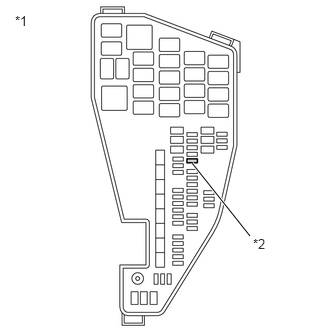
- Remove the INV W/PMP fuse from No. 1 engine room relay block and No. 1 junction block assembly.
*1 No. 1 Engine Room Relay Block and No. 1 Junction Block Assembly *2 INV W/PMP Fuse - According to the display on the GTS, read the Data List.
Powertrain > Hybrid Control > Data List
Tester Display Inverter Water Pump Revolution OK
Tester Display Condition Specified Condition Inverter Water Pump Revolution Ignition switch ON 200 rpm or less - Turn the ignition switch off.
- Install the INV W/PMP fuse.
Result
Proceed to OK NG
Result:
NG
REPLACE HYBRID VEHICLE CONTROL ECU. Refer to REMOVAL [12/2019 - 10/2022] , or refer to REMOVAL [10/2022 - 11/2023]
Result:
OK
See step 10
- Remove the INV W/PMP fuse from No. 1 engine room relay block and No. 1 junction block assembly.
- CHECK HARNESS AND CONNECTOR (HYBRID VEHICLE CONTROL ECU - INVERTER WATER PUMP ASSEMBLY)
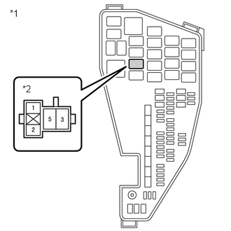
- Remove the INV W/PMP relay from No. 1 engine room relay block and No. 1 junction block assembly.
*1 No. 1 Engine Room Relay Block and No. 1 Junction Block Assembly *2 INV W/PMP Relay Holder - Disconnect the A31 hybrid vehicle control ECU connector.
- Connect terminals 3 and 5 of the INV W/PMP relay holder.
HINT:
Make a short circuit between terminals 3 and 5 to supply +B voltage to the inverter water pump.
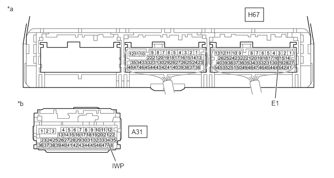
- Measure the voltage according to the value(s) in the table below.
*a Component with harness connected
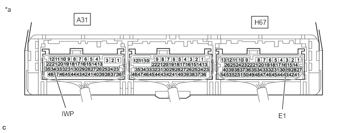
(Hybrid Vehicle Control ECU)*b Front view of wire harness connector
(to Hybrid Vehicle Control ECU)Standard Voltage
Tester Connection Condition Specified Condition A31-34 (IWP) - H67-3 (E1) INV W/PMP relay holder terminals 3 and 5 connected
Ignition switch off11 to 14 V NOTE:Make sure to check for and clear DTCs after performing this inspection.
- Reconnect the A31 hybrid vehicle control ECU connector.
- Install the INV W/PMP relay.
Result
Proceed to OK NG
Result:
NG
See step 12
Result:
OK
See step 11
- Remove the INV W/PMP relay from No. 1 engine room relay block and No. 1 junction block assembly.
- CHECK HYBRID VEHICLE CONTROL ECU (CHECK WAVEFORM)
- Connect an oscilloscope between the hybrid vehicle control ECU terminals specified in the table below.
- Turn the ignition switch to ON.
- Check the waveform while turning the ignition switch to ON.
*a Component with harness connected
(Hybrid Vehicle Control ECU)- - Item Content Terminal A31-34 (IWP) - H67-3 (E1) Equipment Setting 5 V/DIV., 50 ms./DIV. Condition Ignition switch ON OK
Waveform duty ratio is between 3% and 9%.
- Turn the ignition switch off.
Result
Proceed to OK NG
Result:
NG
REPLACE HYBRID VEHICLE CONTROL ECU. Refer to REMOVAL [12/2019 - 10/2022] , or refer to REMOVAL [10/2022 - 11/2023]
Result:
OK
See step 12
- REPLACE INVERTER WATER PUMP ASSEMBLY
Refer to REMOVAL [12/2019 - ]
Result
Proceed to NEXT Result:
NEXT
See step 13
- ADD HV COOLANT AND PERFORM AIR BLEEDING
- After replacing the inverter water pump assembly, add HV coolant and perform air bleeding.
Refer to REPLACEMENT [12/2019 - ]
Result
Proceed to NEXT
Result:
NEXT
END
- After replacing the inverter water pump assembly, add HV coolant and perform air bleeding.