DTC P0340-00: Camshaft Position Sensor "A" Circuit Bank 1 or Single Sensor; DTC P0340-31: Camshaft Position Sensor "A" Circuit Bank 1 or Single Sensor No Signal [12/2019 - 11/2023]: Procedure
- CHECK DTC OUTPUT (ENGINE)
- Check for DTCs.
Powertrain > Engine > Trouble Codes
Result
Result Proceed to SFI system DTCs are not output. A Any of the following DTCs are also output. B Relevant DTC P0340-11 Camshaft Position Sensor "A" Bank 1 or Single Sensor Circuit Short to Ground P0340-15 Camshaft Position Sensor "A" Bank 1 or Single Sensor Circuit Short to Battery or Open P0340-31 Camshaft Position Sensor "A" Bank 1 or Single Sensor No Signal - Turn the ignition switch off.
Result:
B
GO TO DTC CHART (SFI SYSTEM)
Refer to DIAGNOSTIC TROUBLE CODE CHART [12/2019 - 09/2020] , or refer to DIAGNOSTIC TROUBLE CODE CHART [09/2020 - 10/2021] , or refer to DIAGNOSTIC TROUBLE CODE CHART [10/2021 - 10/2022] , or refer to DIAGNOSTIC TROUBLE CODE CHART [10/2022 - 11/2023]
Result:
A
See step 2
- Check for DTCs.
- CHECK DTC OUTPUT (MOTOR GENERATOR)
- Check for DTCs.
Powertrain > Motor Generator > Trouble Codes
Result
Result Proceed to None of the following DTCs are output. A Any of the following DTCs are also output. B Relevant DTC P06B0-1C Generator Control Module Position Sensor REF Power Source Circuit Voltage Out of Range P06D6-1C Generator Control Module Offset Power Circuit Voltage Out of Range P0A1B-1F Generator Control Module Circuit Intermittent P1C2B-49 Drive Motor "A" Control Module A/D Converter Circuit Internal Electronic Failure P1C2B-1C Drive Motor "A" Control Module A/D Converter Circuit Voltage Out of Range P1CAD-49 Drive Motor "A" Position Sensor Internal Electronic Failure P1CB0-38 Drive Motor "A" Position Sensor REF Signal Frequency Incorrect P3134-87 Communication Error from Drive Motor "A" to Generator Missing Message P3134-83 Communication Error from Drive Motor "A" to Generator Value of Signal Protection Calculation Incorrect P3134-86 Communication Error from Drive Motor "A" to Generator Signal Invalid HINT:
P0340-00 or P0340-31 may be stored due to a malfunction which also causes the DTCs in the preceding table to be stored. In this case, first troubleshoot the output DTCs in the preceding table. Then, perform a test to attempt to reproduce the problems, and check that no DTCs are output.
- Turn the ignition switch off.
Result:
B
GO TO DTC CHART (MOTOR GENERATOR CONTROL SYSTEM) . Refer to DIAGNOSTIC TROUBLE CODE CHART [12/2019 - 10/2021] , or refer to DIAGNOSTIC TROUBLE CODE CHART [10/2021 - 11/2023]
Result:
A
See step 3
- Check for DTCs.
- CHECK CONNECTOR CONNECTION CONDITION (INVERTER WITH CONVERTER ASSEMBLY CONNECTOR)
See step 3
Result
Result Proceed to OK A NG (The connector is not connected securely.) B NG (The terminals are not making secure contact or are deformed, or water or foreign matter exists in the connector.) C Result:
B
CONNECT SECURELY
Result:
C
REPAIR OR REPLACE HARNESS OR CONNECTOR
Result:
A
See step 4
- CHECK CONNECTOR CONNECTION CONDITION (ECM CONNECTOR)
See step 4
Result
Proceed to OK NG Result:
NG
CONNECT SECURELY
Result:
OK
See step 5
- CHECK HARNESS AND CONNECTOR (INVERTER WITH CONVERTER ASSEMBLY - ECM) WARNING:
Be sure to wear insulated gloves.
- Check that the service plug grip is not installed.NOTE:
After removing the service plug grip, do not turn the ignition switch to ON (READY), unless instructed by the repair information because this may cause a malfunction.
- Disconnect the A55 inverter with converter assembly connector.
- Disconnect the A27 ECM connector.
- Connect the cable to the negative (-) auxiliary battery terminal.
- Turn the ignition switch to ON.
- Measure the voltage according to the value(s) in the table below.
Standard Voltage
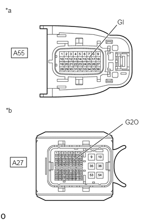
Tester Connection Condition Specified Condition A55-16 (GI) - Body ground Ignition switch ON Below 1 V NOTE:Turning the ignition switch to ON with the inverter with converter assembly connector and ECM connector disconnected causes other DTCs to be stored. Clear the DTCs after performing this inspection.
*a Front view of wire harness connector
(to Inverter with Converter Assembly)*b Front view of wire harness connector
(to ECM) - Turn the ignition switch off.
- Measure the resistance according to the value(s) in the table below.
Standard Resistance (Check for Open)
Tester Connection Condition Specified Condition A55-16 (GI) - A27-24 (G2O) Ignition switch off Below 1 Ω Standard Resistance (Check for Short)
Tester Connection Condition Specified Condition A55-16 (GI) or A27-24 (G2O) - Body ground and other terminals Ignition switch off 10 kΩ or higher - Disconnect the cable from the negative (-) auxiliary battery terminal.
- Reconnect the A27 ECM connector.
- Reconnect the A55 inverter with converter assembly connector.
Result
Proceed to OK NG
Result:
NG
REPAIR OR REPLACE HARNESS OR CONNECTOR
Result:
OK
See step 6
- Check that the service plug grip is not installed.
- CHECK ECM
- Disconnect the A27 ECM connector.
- Measure the resistance according to the value(s) in the table below.
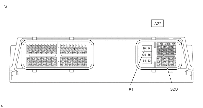
*a Component without harness connected
(ECM)- - Standard Resistance
Tester Connection Condition Specified Condition A27-24 (G2O) - A27-10 (E1) Ignition switch off 10 kΩ or higher - Reconnect the A27 ECM connector.
Result
Proceed to OK NG
Result:
OK
REPLACE INVERTER WITH CONVERTER ASSEMBLY
Refer to REMOVAL [12/2019 - 10/2022] , or refer to REMOVAL [10/2022 - 11/2023]
Result:
NG
REPLACE ECM
Refer to REMOVAL [12/2019 - 10/2022] , or refer to REMOVAL [10/2022 - 11/2023]