DTC P1C81-49: High Voltage Power Resource Circuit Consumption Circuit Short; DTC P1C82-49: High Voltage Power Resource Circuit Over Loading [12/2019 - 11/2023]: Procedure
- CHECK DTC OUTPUT (HYBRID CONTROL, MOTOR GENERATOR)
- Check for DTCs.
Powertrain > Hybrid Control > Trouble Codes
Powertrain > Motor Generator > Trouble Codes
Result
Result Proceed to P1C81-49 or P1C82-49 only is output, or DTCs except the ones in the tables below are also output. A DTCs of Hybrid Control System in the tables below are output. B DTCs of Motor Generator Control System in the tables below are output. C Malfunction Content System Relevant DTC Microcomputer malfunction Hybrid Control System P0606-47 Hybrid/EV Powertrain Control Module Processor Watchdog / Safety MCU Failure P0AFC-96 Hybrid/EV Battery Sensor Module Component Internal Failure P0AFC-00 Hybrid/EV Battery Sensor Module Power source circuit malfunction Hybrid Control System P0AFC-16 Hybrid/EV Battery Sensor Module Circuit Voltage Below Threshold Communication system malfunction Hybrid Control System U029A-87 Lost Communication with Hybrid/EV Battery Sensor Module Missing Message Sensor and actuator circuit malfunction Hybrid Control System P0ABF-11 Hybrid/EV Battery Current Sensor "A" Circuit Short to Ground P0ABF-15 Hybrid/EV Battery Current Sensor "A" Circuit Short to Auxiliary Battery or Open P0B3B-14 Hybrid/EV Battery Voltage Sensor "A" Circuit Short to Ground or Open P0B40-14 Hybrid/EV Battery Voltage Sensor "B" Circuit Short to Ground or Open P0B45-14 Hybrid/EV Battery Voltage Sensor "C" Circuit Short to Ground or Open P0B4A-14 Hybrid/EV Battery Voltage Sensor "D" Circuit Short to Ground or Open P0B4F-14 Hybrid/EV Battery Voltage Sensor "E" Circuit Short to Ground or Open P0B54-14 Hybrid/EV Battery Voltage Sensor "F" Circuit Short to Ground or Open P0B59-14 Hybrid/EV Battery Voltage Sensor "G" Circuit Short to Ground or Open P0B5E-14 Hybrid/EV Battery Voltage Sensor "H" Circuit Short to Ground or Open P0B63-14 Hybrid/EV Battery Voltage Sensor "I" Circuit Short to Ground or Open P0B68-14 Hybrid/EV Battery Voltage Sensor "J" Circuit Short to Ground or Open P0B6D-14 Hybrid/EV Battery Voltage Sensor "K" Circuit Short to Ground or Open P0B72-14 Hybrid/EV Battery Voltage Sensor "L" Circuit Short to Ground or Open P0B77-14 Hybrid/EV Battery Voltage Sensor "M" Circuit Short to Ground or Open P308A-13 Hybrid/EV Battery Voltage Sensor All Circuit Open P0AFC-62 Hybrid/EV Battery Sensor Module Signal Compare Failure P0B23-1C Hybrid/EV Battery "A" Voltage Sensor Voltage Out of Range P308A-12 Hybrid/EV Battery Voltage Sensor All Circuit Short to Auxiliary Battery P0ABF-00 Hybrid/EV Battery Current Sensor "A" Circuit Range/Performance P0ABF-28 Hybrid/EV Battery Current Sensor "A" Signal Bias Level Out of Range / Zero Adjustment Failure P0ABF-2A Hybrid/EV Battery Current Sensor "A" Signal Stuck In Range Motor Generator Control System P0A11-14 DC/DC Converter Enable Circuit Short to Ground or Open P0A11-12 DC/DC Converter Enable Circuit Short to Battery P1CCC-96 DC/DC Converter Enable Component Internal Failure System malfunction Motor Generator Control System P0D33-19 DC/DC Converter Circuit Current Above Threshold HINT:
- P1C81-49 or P1C82-49 may be output as a result of the malfunction indicated by the DTCs above.
- The chart above is listed in inspection order of priority.
- Check DTCs that are output at the same time by following the listed order. (The main cause of the malfunction can be determined without performing unnecessary inspections.)
- P1C81-49 or P1C82-49 may be output as a result of the malfunction indicated by the DTCs above.
- Turn the ignition switch off.
Result:
B
GO TO DTC CHART (HYBRID CONTROL SYSTEM)
Refer to DIAGNOSTIC TROUBLE CODE CHART [12/2019 - 09/2020] , or refer to DIAGNOSTIC TROUBLE CODE CHART [09/2020 - 10/2021] , or refer to DIAGNOSTIC TROUBLE CODE CHART [10/2021 - 11/2023]
Result:
C
GO TO DTC CHART (MOTOR GENERATOR CONTROL SYSTEM) . Refer to DIAGNOSTIC TROUBLE CODE CHART [12/2019 - 10/2021] , or refer to DIAGNOSTIC TROUBLE CODE CHART [10/2021 - 11/2023]
Result:
A
See step 2
- Check for DTCs.
- CHECK COMPRESSOR WITH MOTOR ASSEMBLY WARNING:
Be sure to wear insulated gloves.
- Check that the service plug grip is not installed.NOTE:
After removing the service plug grip, do not turn the ignition switch to ON (READY), unless instructed by the repair information because this may cause a malfunction.
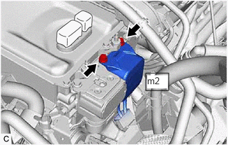
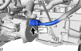
- Disconnect the HV air conditioning wire connector from the inverter with converter assembly.
- Measure the resistance according to the value(s) in the table below.
Standard Resistance
Tester Connection
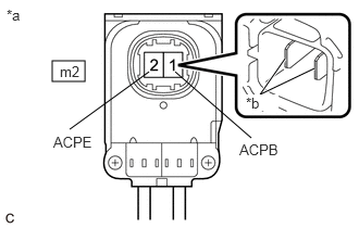
(Tester Probe Polarity)Condition Specified Condition m2-2 (ACPE) (Negative (-) probe) - m2-1 (ACPB) (Positive (+) probe) Ignition switch off 100 kΩ or higher NOTE:- Do not use a megohmmeter.
- Read the resistance after the value has stabilized.
- Be sure to inspect with connecting the tester probes to the tips of the terminal.
*a HV Air Conditioning Wire
(Inverter with Converter Assembly Side)*b Tip of Terminal - Reconnect the HV air conditioning wire connector.
Result
Proceed to OK NG
Result:
NG
See step 4
Result:
OK
See step 3
- Check that the service plug grip is not installed.
- CHECK FLOOR UNDER WIRE WARNING:
Be sure to wear insulated gloves.
- Check that the service plug grip is not installed.NOTE:
After removing the service plug grip, do not turn the ignition switch to ON (READY), unless instructed by the repair information because this may cause a malfunction.
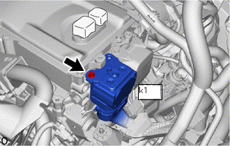
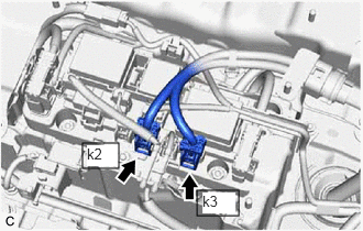
- Disconnect the HV floor under wire connector from the inverter with converter assembly.
- Measure the resistance according to the value(s) in the table below.
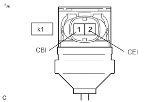
*a HV Floor Under Wire
(Inverter with Converter Assembly Side)Standard Resistance
Tester Connection Condition Specified Condition k1-1 (CBI) - k1-2 (CEI) Ignition switch off 10 kΩ or higher NOTE:Be sure not to damage or deform the terminal being inspected.
- Reconnect the HV floor under wire connector.
Result
Proceed to OK NG
Result:
OK
REPLACE INVERTER WITH CONVERTER ASSEMBLY
Refer to REMOVAL [12/2019 - 10/2022] , or refer to REMOVAL [10/2022 - 11/2023]
Result:
NG
See step 5
- Check that the service plug grip is not installed.
- CHECK HV AIR CONDITIONING WIRE WARNING:
Be sure to wear insulated gloves.
- Check that the service plug grip is not installed.NOTE:
After removing the service plug grip, do not turn the ignition switch to ON (READY), unless instructed by the repair information because this may cause a malfunction.
- Disconnect the HV air conditioning wire connector from the inverter with converter assembly.
- Disconnect the HV air conditioning wire connector from the compressor with motor assembly.
Refer to REMOVAL [12/2019 - 10/2022] , or refer to REMOVAL [10/2022 - 11/2023]
- Measure the resistance according to the value(s) in the table below.
Standard Resistance
Tester Connection Condition Specified Condition m2-2 (ACPE) - m2-1 (ACPB) Ignition switch off 10 kΩ or higher *a HV Air Conditioning Wire
(Inverter with Converter Assembly Side)*b Tip of Terminal NOTE:Be sure to inspect with connecting the tester probes to the tips of the terminal.
- Reconnect the HV air conditioning wire connector to the inverter with converter assembly.
- Reconnect the HV air conditioning wire to the compressor with motor assembly.
Result
Proceed to OK NG
Result:
OK
REPLACE COMPRESSOR WITH MOTOR ASSEMBLY
Refer to REMOVAL [12/2019 - 10/2022] , or refer to REMOVAL [10/2022 - 11/2023]
Result:
NG
REPLACE HV AIR CONDITIONING WIRE
- Check that the service plug grip is not installed.
- CHECK FLOOR UNDER WIRE WARNING:
Be sure to wear insulated gloves.
- Check that the service plug grip is not installed.NOTE:
After removing the service plug grip, do not turn the ignition switch to ON (READY), unless instructed by the repair information because this may cause a malfunction.
- Remove the No. 10 HV battery shield panel.
Refer to REMOVAL [12/2019 - 10/2022] , or refer to REMOVAL [10/2022 - 11/2023]
- Disconnect the HV floor under wire connectors from the HV battery junction block assembly.
- Disconnect the HV floor under wire connector from the inverter with converter assembly.
- Measure the resistance according to the value(s) in the table below.
Standard Resistance
Tester Connection Condition Specified Condition k1-1 (CBI) - k1-2 (CEI) Ignition switch off 10 kΩ or higher *a HV Floor Under Wire
(Inverter with Converter Assembly Side)NOTE:Be sure not to damage or deform the terminal being inspected.
- Reconnect the HV floor under wire connector to the inverter with converter assembly.
- Reconnect the HV floor under wire connectors to the HV battery junction block assembly.
- Install the No. 10 HV battery shield panel.
Result
Result Proceed to OK (w/o 1500W voltage inverter) A OK (w/ 1500W voltage inverter) B NG C
Result:
A
REPLACE HV BATTERY JUNCTION BLOCK ASSEMBLY
Refer to REMOVAL [12/2019 - 10/2022] , or refer to REMOVAL [10/2022 - 11/2023]
Result:
C
REPLACE FLOOR UNDER WIRE
Refer to REMOVAL [12/2019 - 10/2022] , or refer to REMOVAL [10/2022 - 11/2023]
Result:
B
See step 6
- Check that the service plug grip is not installed.
- CHECK NO. 2 FLOOR WIRE WARNING:
Be sure to wear insulated gloves.
- Check that the service plug grip is not installed.NOTE:
After removing the service plug grip, do not turn the ignition switch to ON (READY), unless instructed by the repair information because this may cause a malfunction.
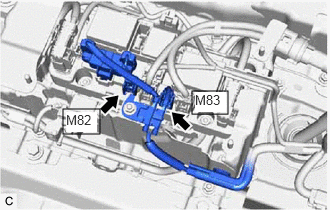
- Disconnect the M82 and M83 No. 2 floor wire connectors from the HV battery junction block assembly.
- Measure the resistance according to the value(s) in the table below.
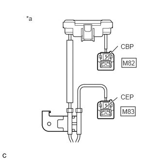
*a No. 2 Floor Wire
(HV Battery Junction Block Assembly Side)Standard Resistance
Tester Connection Condition Specified Condition M82-1 (CBP) - M83-1 (CEP) Ignition switch off 10 kΩ or higher - Reconnect the M82 and M83 No. 2 floor wire connectors.
Result
Proceed to OK NG
Result:
OK
REPLACE HV BATTERY JUNCTION BLOCK ASSEMBLY
Refer to REMOVAL [12/2019 - 10/2022] , or refer to REMOVAL [10/2022 - 11/2023]
Result:
NG
See step 7
- Check that the service plug grip is not installed.
- CHECK NO. 2 FLOOR WIRE WARNING:
Be sure to wear insulated gloves.
- Check that the service plug grip is not installed.NOTE:
After removing the service plug grip, do not turn the ignition switch to ON (READY), unless instructed by the repair information because this may cause a malfunction.
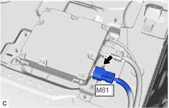
- Disconnect the M81 voltage inverter assembly connector.
- Disconnect the M82 and M83 No. 2 floor wire connectors from the HV battery junction block assembly.
- Measure the resistance according to the value(s) in the table below.
*a No. 2 Floor Wire
(HV Battery Junction Block Assembly Side)Standard Resistance
Tester Connection Condition Specified Condition M82-1 (CBP) - M83-1 (CEP) Ignition switch off 10 kΩ or higher - Reconnect the M82 and M83 No. 2 floor wire connectors.
- Reconnect the M81 voltage inverter assembly connector.
Result
Proceed to OK NG
Result:
OK
REPLACE VOLTAGE INVERTER ASSEMBLY
Refer to REMOVAL [12/2019 - 10/2022] , or refer to REMOVAL [10/2022 - 11/2023]
Result:
NG
REPLACE NO. 2 FLOOR WIRE
- Check that the service plug grip is not installed.