DTC P1C85-49: High Voltage Power Resource Internal Electronic Failure [12/2019 - 11/2023]: Procedure
- CHECK DTC OUTPUT (HYBRID CONTROL)
- Check for DTCs.
Powertrain > Hybrid Control > Trouble Codes
Result
Result Proceed to P1C85-49 only is output. A DTCs other than P1C85-49 is also output. B - Turn the ignition switch off.
Result:
B
GO TO DTC CHART (HYBRID CONTROL SYSTEM)
Refer to DIAGNOSTIC TROUBLE CODE CHART [12/2019 - 09/2020] , or refer to DIAGNOSTIC TROUBLE CODE CHART [09/2020 - 10/2021] , or refer to DIAGNOSTIC TROUBLE CODE CHART [10/2021 - 11/2023]
Result:
A
See step 2
- Check for DTCs.
- READ VALUE USING GTS (HYBRID BATTERY CURRENT)
- Read the Data List.
Powertrain > Hybrid Control > Data List
Tester Display Hybrid Battery Current Result
Result Proceed to The value of Hybrid Battery Current is between -4 A and 4 A A Other than above B - Turn the ignition switch off.
Result:
A
REPLACE HYBRID VEHICLE CONTROL ECU
Refer to REMOVAL [12/2019 - 10/2022] , or refer to REMOVAL [10/2022 - 11/2023]
Result:
B
See step 3
- Read the Data List.
- CHECK HARNESS AND CONNECTOR (BATTERY VOLTAGE SENSOR - HV BATTERY JUNCTION BLOCK ASSEMBLY) WARNING:
Be sure to wear insulated gloves.
- Check that the service plug grip is not installed.NOTE:
After removing the service plug grip, do not turn the ignition switch to ON (READY), unless instructed by the repair information because this may cause a malfunction.
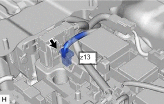
- Disconnect the z13 battery current sensor connector.NOTE:
Before disconnecting the connector, check that it is not loose or disconnected.
- Remove the HV battery junction block assembly.
Refer to REMOVAL [12/2019 - 10/2022] , or refer to REMOVAL [10/2022 - 11/2023]
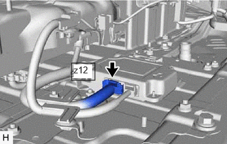
- Disconnect the z12 battery voltage sensor connector.NOTE:
Before disconnecting the connector, check that it is not loose or disconnected.
- Measure the resistance according to the value(s) in the tables below.
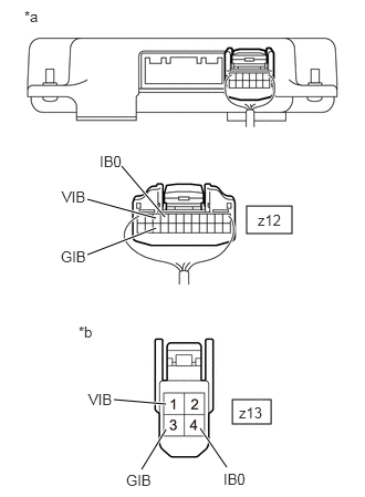
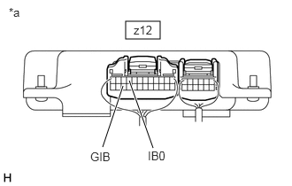
*a Rear view of wire harness connector
(to Battery Voltage Sensor)*b Front view of wire harness connector
(to HV Battery Junction Block Assembly (Battery Current Sensor))Standard Resistance (Check for Open)
Tester Connection Condition Specified Condition z12-9 (IB0) - z13-4 (IB0) Ignition switch off Below 1 Ω z12-22 (GIB) - z13-3 (GIB) Ignition switch off Below 1 Ω z12-10 (VIB) - z13-1 (VIB) Ignition switch off Below 1 Ω Standard Resistance (Check for Short)
Tester Connection Condition Specified Condition z12-9 (IB0) or z13-4 (IB0) - Body ground and other terminals Ignition switch off 10 kΩ or higher z12-22 (GIB) or z13-3 (GIB) - Body ground and other terminals Ignition switch off 10 kΩ or higher z12-10 (VIB) or z13-1 (VIB) - Body ground and other terminals Ignition switch off 10 kΩ or higher - Reconnect the z12 battery voltage sensor connector.
- Install the HV battery junction block assembly.
- Reconnect the z13 battery current sensor connector.
Result
Proceed to OK NG
Result:
NG
REPLACE HYBRID BATTERY THERMISTOR (WIRE HARNESS OR CONNECTOR)
Refer to REMOVAL [12/2019 - 10/2022] , or refer to REMOVAL [10/2022 - 11/2023]
Result:
OK
See step 4
- Check that the service plug grip is not installed.
- CHECK HV BATTERY JUNCTION BLOCK ASSEMBLY (BATTERY CURRENT SENSOR (IB)) WARNING:
Be sure to wear insulated gloves.
- Check that the service plug grip is not installed.NOTE:
After removing the service plug grip, do not turn the ignition switch to ON (READY), unless instructed by the repair information because this may cause a malfunction.
- Disconnect the z13 battery current sensor connector.NOTE:
Before disconnecting the connector, check that it is not loose or disconnected.
- Remove the HV battery junction block assembly.
Refer to REMOVAL [12/2019 - 10/2022] , or refer to REMOVAL [10/2022 - 11/2023]
- Connect the z13 battery current sensor connector.
- Connect the cable to the negative (-) auxiliary battery terminal.
- Turn the ignition switch to ON.
- Using a Toyota electrical tester set to 40 V, measure the VIB voltage according to the value(s) in the table below.
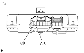
*a Component with harness connected
(Battery Voltage Sensor)Tester Connection Switch Condition z12-10 (VIB) - z12-22 (GIB) Ignition switch ON NOTE:- Turning the ignition switch to ON with the service plug grip removed causes other DTCs to be stored. Clear the DTCs after performing this inspection.
- Be sure to set the Toyota electrical tester to 40 V when performing this test.
- Using a Toyota electrical tester set to 4 V, measure the IB0 voltage according to the value(s) in the table below.
*a Component with harness connected
(Battery Voltage Sensor)Tester Connection Switch Condition z12-9 (IB0) - z12-22 (GIB) Ignition switch ON NOTE:Be sure to set the Toyota electrical tester to 4 V when performing this test.
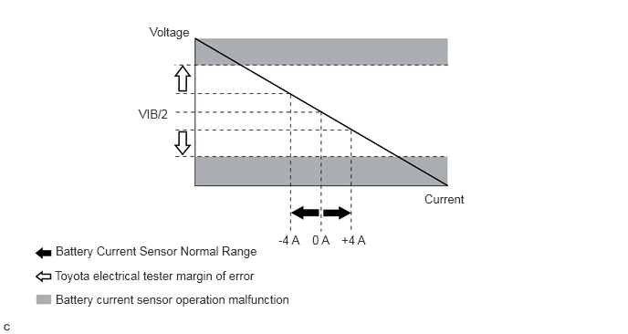
- Compare the measured values of the IB0 terminal voltage and VIB terminal voltage using the following formula:
IB0 voltage - VIB Voltage / 2 = less than 0.081 V IB0 voltage - VIB Voltage / 2 = -0.081 V or higher Result
Result Proceed to Within the specified range above A Other than above B - Turn the ignition switch off.
- Disconnect the cable from the negative (-) auxiliary battery terminal.
- Install the HV battery junction block assembly.
HINT:
When the ignition switch is ON, the actual current will be approximately 0 A. The following graph shows the relation of the actual output voltage between the battery current sensor terminal IB0 and the actual current used for DTC judgment.
Result:
B
REPLACE HV BATTERY JUNCTION BLOCK ASSEMBLY
Refer to REMOVAL [12/2019 - 10/2022] , or refer to REMOVAL [10/2022 - 11/2023]
Result:
A
See step 5
- Check that the service plug grip is not installed.
- REPLACE BATTERY VOLTAGE SENSOR
Refer to REMOVAL [12/2019 - 10/2022] , or refer to REMOVAL [10/2022 - 11/2023]
Result
Proceed to NEXT Result:
NEXT
See step 6
- SIMULATION TEST
- Clear the DTCs and Freeze Frame Data.
Powertrain > Hybrid Control > Clear DTCs
- Drive the vehicle on urban roads for approximately 10 minutes.
- Turn the ignition switch off and wait for 2 minutes or more.
- Turn the ignition switch to ON and wait for 30 seconds or more.
Result
Proceed to NEXT
Result:
NEXT
See step 7
- Clear the DTCs and Freeze Frame Data.
- RECONFIRM DTC OUTPUT (HYBRID CONTROL)
- Read output DTCs.
Powertrain > Hybrid Control > Trouble Codes
Result
Result Proceed to DTCs are not output A P1C85-49 is output B - Turn the ignition switch off.
Result:
A
END
Result:
B
REPLACE HV BATTERY JUNCTION BLOCK ASSEMBLY
Refer to REMOVAL [12/2019 - 10/2022] , or refer to REMOVAL [10/2022 - 11/2023]
- Read output DTCs.