DTC P1CFF-62: Hybrid/EV Battery Current/DC/DC Converter Current Signal Compare Failure [12/2019 - 11/2023]: Procedure
- CHECK DTC OUTPUT
- Check for DTCs.
Powertrain > Hybrid Control > Trouble Codes
Powertrain > Motor Generator > Trouble Codes
Result
Result Proceed to P1CFF-62 only is output, or DTCs except the ones in the table below are also output. A DTCs of hybrid control system in the tables below are output. B DTCs of motor generator control system in the tables below are output. C TABLE 1Malfunction Content System Relevant DTC Insulation Malfunction Hybrid control system P1C7C-49 Hybrid/EV Battery Voltage System Isolation (A/C Area) Internal Electronic Failure P1C7D-49 Hybrid/EV Battery Voltage System Isolation (Hybrid/EV Battery Area) Internal Electronic Failure P1C7E-49 Hybrid/EV Battery Voltage System Isolation (Transaxle Area) Internal Electronic Failure P1C7F-49 Hybrid/EV Battery Voltage System Isolation (Direct Current Area) Internal Electronic Failure HV Battery Malfunction Hybrid control system P0ABF-00 Hybrid/EV Battery Current Sensor "A" Circuit Range/Performance P0ABF-11 Hybrid/EV Battery Current Sensor "A" Circuit Short to Ground P0ABF-15 Hybrid/EV Battery Current Sensor "A" Circuit Short to Auxiliary Battery or Open P0ABF-28 Hybrid/EV Battery Current Sensor "A" Signal Bias Level Out of Range / Zero Adjustment Failure P0ABF-2A Hybrid/EV Battery Current Sensor "A" Signal Stuck In Range P0AFC-00 Hybrid/EV Battery Sensor Module P0AFC-16 Hybrid/EV Battery Sensor Module Circuit Voltage Below Threshold P0AFC-62 Hybrid/EV Battery Sensor Module Signal Compare Failure P0AFC-96 Hybrid/EV Battery Sensor Module Component Internal Failure P1CBB-12 Hybrid/EV Battery Current Sensor Power Supply Circuit Short to Auxiliary Battery P1CBB-14 Hybrid/EV Battery Current Sensor Power Supply Circuit Short to Ground or Open U029A-87 Lost Communication with Hybrid/EV Battery Sensor Module Missing Message TABLE 2Malfunction Content System Relevant DTC Microcomputer malfunction Motor generator control system P0A1A-47 Generator Control Module Watchdog / Safety MC Failure P0A1A-49 Generator Control Module Internal Electronic Failure P0A1B-1F Generator Control Module Circuit Intermittent P1C2A-1C Generator A/D Converter Circuit Circuit Voltage Out of Range P1C2A-49 Generator A/D Converter Circuit Internal Electronic Failure P1C2B-1C Drive Motor "A" Control Module A/D Converter Circuit Voltage Out of Range P1C2B-49 Drive Motor "A" Control Module A/D Converter Circuit Internal Electronic Failure P3133-83 Communication Error from Generator to Drive Motor "A" Value of Signal Protection Calculation Incorrect P3133-86 Communication Error from Generator to Drive Motor "A" Signal Invalid P3133-87 Communication Error from Generator to Drive Motor "A" Missing Message P3134-83 Communication Error from Drive Motor "A" to Generator Value of Signal Protection Calculation Incorrect P3134-86 Communication Error from Drive Motor "A" to Generator Signal Invalid P3134-87 Communication Error from Drive Motor "A" to Generator Missing Message Hybrid control system P0A1B-49 Drive Motor "A" Control Module Internal Electronic Failure Power source circuit malfunction Motor generator control system P06B0-1C Generator Control Module Position Sensor REF Power Source Circuit Voltage Out of Range P06D6-1C Generator Control Module Offset Power Circuit Voltage Out of Range Communication malfunction Motor generator control system P3124-87 Lost Communication between Drive Motor "A" and HV ECU Missing Message Hybrid control system P3123-87 Lost Communication with Drive Motor Control Module "A" from Hybrid/EV Control Module Missing Message Sensor and actuator circuit malfunction Motor generator control system P0E51-11 DC/DC Converter Current Sensor Circuit Short to Ground P0E51-15 DC/DC Converter Current Sensor Circuit Short to Battery or Open P0E51-28 DC/DC Converter Current Sensor Signal Bias Level Out of Range / Zero Adjustment Failure HINT:
- P1CFF-62 may be output as a result of the malfunction indicated by the DTCs above.
- The chart above is listed in inspection order of priority.
- Check DTCs that are output at the same time by following the listed order. (The main cause of the malfunction can be determined without performing unnecessary inspections.)
- P1CFF-62 may be output as a result of the malfunction indicated by the DTCs above.
- Turn the ignition switch off.
Result:
B
GO TO DTC CHART (HYBRID CONTROL SYSTEM)
Refer to DIAGNOSTIC TROUBLE CODE CHART [12/2019 - 09/2020] , or refer to DIAGNOSTIC TROUBLE CODE CHART [09/2020 - 10/2021] , or refer to DIAGNOSTIC TROUBLE CODE CHART [10/2021 - 11/2023]
Result:
C
GO TO DTC CHART (MOTOR GENERATOR CONTROL SYSTEM) . Refer to DIAGNOSTIC TROUBLE CODE CHART [12/2019 - 10/2021] , or refer to DIAGNOSTIC TROUBLE CODE CHART [10/2021 - 11/2023]
Result:
A
See step 2
- Check for DTCs.
- SIMULATION TEST
- Ensure the safety of the areas in front and at the back of the vehicle.
- Apply the parking brake and secure the wheels using chocks.NOTE:
Perform this test with the AUTO function (shift-linked function) of the electric parking brake system off.
HINT:
When the parking brake indicator (red) is illuminated after the electric parking brake switch assembly has been pulled to the lock side, the maximum amount of braking force is applied if the electric parking brake switch assembly is pulled to the lock side one more time.
- Connect the GTS to the DLC3.
- Turn the ignition switch to ON (READY).
- Depress the brake pedal firmly with your left foot.
- Move the shift lever to D.
- Enter the following menus: Powertrain / Motor Generator / Data List / Hybrid/EV Battery System Current, Inverter Input Current, WIN Control Limit Power.
HINT:
Perform this procedure while making sure that the absolute value of the Data List item WIN Control Limit Power remains higher than 20 kW.
- Depress the brake pedal firmly with your left foot and fully depress the accelerator pedal for 5 seconds, and then release it.WARNING:
Make sure to fully apply the parking brake and firmly depress the brake pedal to prevent the vehicle from moving.
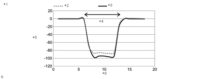
- According to the display on the GTS, read the Data List and monitor the values of "Hybrid/EV Battery System Current" and "Inverter Input Current".
*1 Change in Hybrid/EV Battery System Current and Inverter Input Current When Normal *2 Hybrid/EV Battery System Current *3 Inverter Input Current *4 Accelerator pedal depressed *5 Current [A] *6 Time [Seconds] Result
Result Proceed to OK A NG (Inverter Input Current did not change) B NG (Hybrid/EV Battery System Current did not change) C - Turn the ignition switch off.
Result:
B
REPLACE INVERTER WITH CONVERTER ASSEMBLY
Refer to REMOVAL [12/2019 - 10/2022] , or refer to REMOVAL [10/2022 - 11/2023]
Result:
C
GO TO DTC CHART (P0ABF-00)
Refer to DTC P0ABF-00: Hybrid/EV Battery Current Sensor "A" Circuit Range/Performance [12/2019 - 11/2023]
Result:
A
See step 3
- CHECK CONNECTOR CONNECTION CONDITION (INVERTER WITH CONVERTER ASSEMBLY CONNECTOR)
Refer to PROCEDURE - Step 3
Result
Result Proceed to OK A NG (The connector is not connected securely.) B NG (The terminals are not making secure contact or are deformed, or water or foreign matter exists in the connector.) C Result:
A
REPLACE INVERTER WITH CONVERTER ASSEMBLY
Refer to REMOVAL [12/2019 - 10/2022] , or refer to REMOVAL [10/2022 - 11/2023]
Result:
B
CONNECT SECURELY
Result:
C
REPAIR OR REPLACE HARNESS OR CONNECTOR