DTC P322F-15: Communication Error from Airbag to Generator Circuit Short to Battery or Open [12/2019 - 11/2023]: Procedure
- CHECK DTC OUTPUT (SRS AIRBAG)
See step 1
Result
Result Proceed to Airbag system DTCs are not output. A Airbag system DTCs are output. B Result:
B
GO TO DTC CHART (AIRBAG SYSTEM)
Refer to DIAGNOSTIC TROUBLE CODE CHART [12/2019 - 10/2021] , or refer to DIAGNOSTIC TROUBLE CODE CHART [10/2021 - 11/2023]
Result:
A
See step 2
- CHECK CONNECTOR CONNECTION CONDITION (INVERTER WITH CONVERTER ASSEMBLY CONNECTOR)
Refer to PROCEDURE - Step 3
Result
Result Proceed to OK A NG (The connector is not connected securely.) B NG (The terminals are not making secure contact or are deformed, or water or foreign matter exists in the connector.) C Result:
B
CONNECT SECURELY
Result:
C
REPAIR OR REPLACE HARNESS OR CONNECTOR
Result:
A
See step 3
- CHECK CONNECTOR CONNECTION CONDITION (AIRBAG SENSOR ASSEMBLY CONNECTOR)
See step 3
Result
Proceed to OK NG Result:
NG
CONNECT SECURELY
Result:
OK
See step 4
- CHECK HARNESS AND CONNECTOR (AIRBAG SENSOR ASSEMBLY - BODY GROUND)
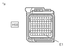
- Disconnect the H58 airbag sensor assembly connector.
- Measure the resistance according to the value(s) in the table below.
*a Front view of wire harness connector
(to Airbag Sensor Assembly)Standard Resistance
Tester Connection Condition Specified Condition H58-33 (E1) - Body ground Ignition switch off Below 1 Ω - Reconnect the H58 airbag sensor assembly connector.
Result
Proceed to OK NG
Result:
NG
REPAIR OR REPLACE HARNESS OR CONNECTOR
Result:
OK
See step 5
- CHECK HARNESS AND CONNECTOR (INVERTER WITH CONVERTER ASSEMBLY - AIRBAG SENSOR ASSEMBLY) WARNING:
Be sure to wear insulated gloves.
- Check that the service plug grip is not installed.NOTE:
After removing the service plug grip, do not turn the ignition switch to ON (READY), unless instructed by the repair information because this may cause a malfunction.
- Disconnect the A55 inverter with converter assembly connector.
- Disconnect the H58 airbag sensor assembly connector.
- Connect the cable to the negative (-) auxiliary battery terminal.
- Turn the ignition switch to ON.
- Measure the voltage according to the value(s) in the table below.
Standard Voltage
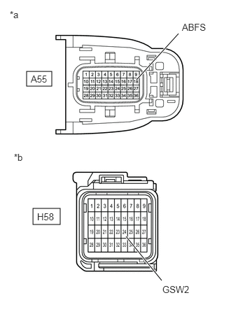
Tester Connection Condition Specified Condition A55-18 (ABFS) - Body ground Ignition switch ON Below 1 V *a Front view of wire harness connector
(to Inverter with Converter Assembly)*b Front view of wire harness connector
(to Airbag Sensor Assembly)NOTE:Turning the ignition switch to ON with the airbag sensor assembly connector and the inverter with converter assembly connector disconnected causes other DTCs to be stored. Clear the DTCs after performing this inspection.
- Turn the ignition switch off.
- Measure the resistance according to the value(s) in the table below.
Standard Resistance (Open)
Tester Connection Condition Specified Condition A55-18 (ABFS) - H58-24 (GSW2) Ignition switch off Below 1 Ω Standard Resistance (Short)
Tester Connection Condition Specified Condition A55-18 (ABFS) or H58-24 (GSW2) - Body ground and other terminals Ignition switch off 10 kΩ or higher - Disconnect the cable from the negative (-) auxiliary battery terminal.
- Reconnect the H58 airbag sensor assembly connector.
- Reconnect the A55 inverter with converter assembly connector.
Result
Proceed to OK NG
Result:
NG
REPAIR OR REPLACE HARNESS OR CONNECTOR
Result:
OK
See step 6
- Check that the service plug grip is not installed.
- REPLACE AIR BAG SENSOR ASSEMBLY
Refer to REMOVAL [12/2019 - 10/2022] , or refer to REMOVAL [10/2022 - 11/2023]
Result
Proceed to NEXT Result:
NEXT
See step 7
- CLEAR DTC
See step 6
Result
Proceed to NEXT Result:
NEXT
See step 8
- CHECK DTC OUTPUT (MOTOR GENERATOR)
- Check for DTCs.
Powertrain > Motor Generator > Trouble Codes
Result
Result Proceed to P322F-15 is not output. A P322F-15 is output. B - Turn the ignition switch off.
Result:
A
COMPLETED
Result:
B
REPLACE INVERTER WITH CONVERTER ASSEMBLY
Refer to REMOVAL [12/2019 - 10/2022] , or refer to REMOVAL [10/2022 - 11/2023]
- Check for DTCs.