ECU Power Source Circuit [12/2019 - 11/2023]: Procedure
- CHECK HYBRID VEHICLE CONTROL ECU (+B1, +B2 VOLTAGE)
- Turn the ignition switch to ON.
- Measure the voltage according to the value(s) in the table below.
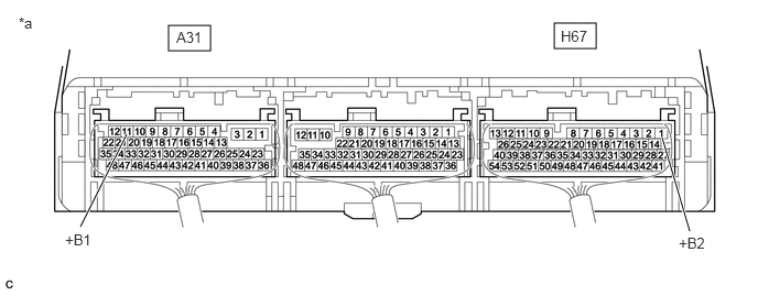
*a Component with harness connected
(Hybrid Vehicle Control ECU)- - Standard Voltage
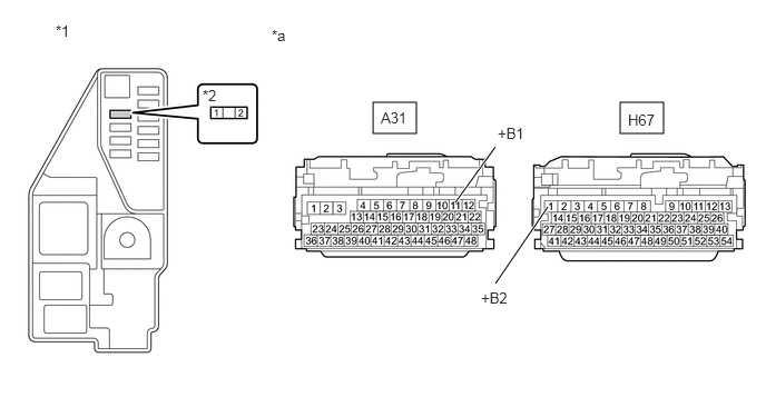
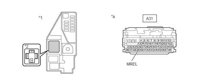
Tester Connection Condition Specified Condition A31-11 (+B1) - Body ground Ignition switch ON 11 to 14 V H67-1 (+B2) - Body ground Ignition switch ON 11 to 14 V - Turn the ignition switch off.
Result
Proceed to OK NG
Result:
NG
See step 3
Result:
OK
See step 2
- CHECK HARNESS AND CONNECTOR (HYBRID VEHICLE CONTROL ECU - BODY GROUND)
- Disconnect the A32 and H67 hybrid vehicle control ECU connectors.
- Measure the resistance according to the value(s) in the table below.
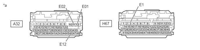
*a Front view of wire harness connector
(to Hybrid Vehicle Control ECU)- - Standard Resistance
Tester Connection Condition Specified Condition H67-3 (E1) - Body ground Always Below 1 Ω A32-12 (E01) - Body ground Always Below 1 Ω A32-11 (E02) - Body ground Always Below 1 Ω A32-34 (E12) - Body ground Always Below 1 Ω - Reconnect the A32 and H67 hybrid vehicle control ECU connectors.
Result
Proceed to OK NG
Result:
OK
GO TO PROBLEM SYMPTOMS TABLE. Refer to PROBLEM SYMPTOMS TABLE [12/2019 - 10/2022] , or refer to PROBLEM SYMPTOMS TABLE [10/2022 - 11/2023]
Result:
NG
REPAIR OR REPLACE HARNESS OR CONNECTOR
- CHECK HYBRID VEHICLE CONTROL ECU (MREL TERMINAL VOLTAGE)
- Turn the ignition switch to ON.
- Measure the voltage according to the value(s) in the table below.
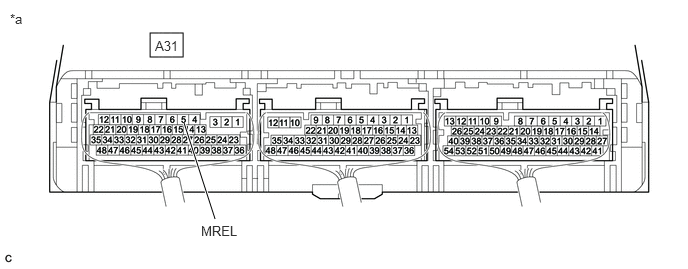
*a Component with harness connected
(Hybrid Vehicle Control ECU)- - Standard Voltage
Tester Connection Condition Specified Condition A31-5 (MREL) - Body ground Ignition switch ON 11 to 14 V - Turn the Ignition switch off.
Result
Proceed to OK NG
Result:
NG
REPLACE HYBRID VEHICLE CONTROL ECU. Refer to REMOVAL [12/2019 - 10/2022] , or refer to REMOVAL [10/2022 - 11/2023]
Result:
OK
See step 4
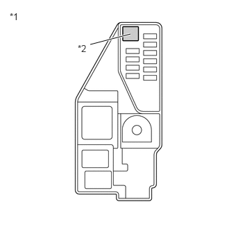
- CHECK FUSE (IGCT NO. 1)
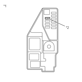
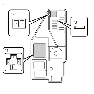
- Remove the IGCT NO. 1 fuse from the No. 5 floor relay block and No. 5 floor junction block assembly.
*1 No. 5 Floor Relay Block and No. 5 Floor Junction Block Assembly *2 IGCT NO. 1 Fuse - Measure the resistance according to the value(s) in the table below.
Standard Resistance
Tester Connection Condition Specified Condition IGCT NO. 1 fuse Always Below 1 Ω - Install the IGCT NO. 1 fuse.
Result
Proceed to OK NG
Result:
NG
See step 11
Result:
OK
See step 5
- Remove the IGCT NO. 1 fuse from the No. 5 floor relay block and No. 5 floor junction block assembly.
- CHECK FUSE (IGCT-IG)
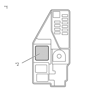
- Remove the IGCT-IG fuse from the No. 5 floor relay block and No. 5 floor junction block assembly.
*1 No. 5 Floor Relay Block and No. 5 Floor Junction Block Assembly *2 IGCT-IG Fuse - Measure the resistance according to the value(s) in the table below.
Standard Resistance
Tester Connection Condition Specified Condition IGCT-IG fuse Always Below 1 Ω - Install the IGCT-IG fuse.
Result
Proceed to OK NG
Result:
NG
See step 12
Result:
OK
See step 6
- Remove the IGCT-IG fuse from the No. 5 floor relay block and No. 5 floor junction block assembly.
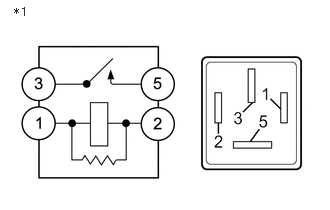
- INSPECT RELAY (IGCT)
- Remove the IGCT relay from the No. 5 floor relay block and No. 5 floor junction block assembly.
*1 No. 5 Floor Relay Block and No. 5 Floor Junction Block Assembly *2 IGCT Relay - Measure the resistance according to the value(s) in the table below.
*1 IGCT Relay Standard Resistance
Tester Connection Condition Specified Condition 3 - 5 Auxiliary battery voltage not applied between terminals 1 and 2 10 kΩ or higher Auxiliary battery voltage applied between terminals 1 and 2 Below 1 Ω - Install the IGCT relay.
Result
Proceed to OK NG
Result:
NG
REPLACE RELAY (IGCT)
Result:
OK
See step 7
- Remove the IGCT relay from the No. 5 floor relay block and No. 5 floor junction block assembly.
- CHECK HARNESS AND CONNECTOR (IGCT NO. 1 FUSE - HYBRID VEHICLE CONTROL ECU)
- Disconnect the A31 and H67 hybrid vehicle control ECU connectors.
- Remove the IGCT NO. 1 fuse from the No. 5 floor relay block and No. 5 floor junction block assembly.
- Measure the resistance according to the value(s) in the table below.
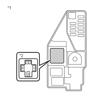
*1 No. 5 Floor Relay Block and No. 5 Floor Junction Block Assembly *2 IGCT NO. 1 Fuse Holder *a Front view of wire harness connectors
(to Hybrid Vehicle Control ECU)- - Standard Resistance
Tester Connection Condition Specified Condition A31-11 (+B1) - 2 (IGCT NO. 1 fuse holder) Always Below 1 Ω H67-1 (+B2) - 2 (IGCT NO. 1 fuse holder) Always Below 1 Ω - Reconnect the A31 and H67 hybrid vehicle control ECU connectors.
- Install the IGCT NO. 1 fuse.
Result
Proceed to OK NG
Result:
NG
REPAIR OR REPLACE HARNESS OR CONNECTOR
Result:
OK
See step 8
- CHECK HARNESS AND CONNECTOR (NO. 5 FLOOR RELAY BLOCK AND NO. 5 FLOOR JUNCTION BLOCK ASSEMBLY)
- Remove the IGCT-IG fuse, IGCT NO. 1 fuse and IGCT relay from the No. 5 floor relay block and No. 5 floor junction block assembly.
- Measure the resistance according to the value(s) in the table below.
Standard Resistance
Tester Connection Condition Specified Condition 3 (IGCT relay holder) - 2 (IGCT-IG fuse holder) Always Below 1 Ω 5 (IGCT relay holder) - 1 (IGCT NO. 1 fuse holder) Always Below 1 Ω *1 No. 5 Floor Relay Block and No. 5 Floor Junction Block Assembly *2 IGCT-IG Fuse Holder *3 IGCT NO. 1 Fuse Holder *4 IGCT Relay Holder - Install the IGCT-IG fuse, IGCT NO. 1 fuse and IGCT relay.
Result
Proceed to OK NG
Result:
NG
REPAIR OR REPLACE HARNESS OR CONNECTOR
Result:
OK
See step 9
- CHECK HARNESS AND CONNECTOR (IGCT RELAY - HYBRID VEHICLE CONTROL ECU)
- Disconnect the A31 hybrid vehicle control ECU connector.
- Remove the IGCT relay from the No. 5 floor relay block and No. 5 floor junction block assembly.
- Measure the resistance according to the value(s) in the table below.
*1 No. 5 Floor Relay Block and No. 5 Floor Junction Block Assembly *2 IGCT Relay Holder *a Front view of wire harness connector
(to Hybrid Vehicle Control ECU)- - Standard Resistance
Tester Connection Condition Specified Condition A31-5 (MREL) - 1 (IGCT relay holder) Always Below 1 Ω A31-5 (MREL) or 1 (IGCT relay holder) - Body ground and other terminals Always 10 kΩ or higher - Install the IGCT relay.
- Reconnect the A31 hybrid vehicle control ECU connector.
Result
Proceed to OK NG
Result:
NG
REPAIR OR REPLACE HARNESS OR CONNECTOR
Result:
OK
See step 10
- CHECK HARNESS AND CONNECTOR (IGCT RELAY - BODY GROUND)
- Remove the IGCT relay from the No. 5 floor relay block and No. 5 floor junction block assembly.
- Measure the resistance according to the value(s) in the table below.
*1 No. 5 Floor Relay Block and No. 5 Floor Junction Block Assembly *2 IGCT Relay Holder Standard Resistance
Tester Connection Condition Specified Condition 2 (IGCT relay holder) - Body ground Always Below 1 Ω - Install the IGCT relay.
Result
Proceed to OK NG
Result:
OK
CHECK FOR INTERMITTENT PROBLEMS. Refer to CHECK FOR INTERMITTENT PROBLEMS [12/2019 - 11/2023]
Result:
NG
REPAIR OR REPLACE HARNESS OR CONNECTOR
- CHECK HARNESS AND CONNECTOR (IGCT NO. 1 FUSE - HYBRID VEHICLE CONTROL ECU)
- Remove the IGCT NO. 1 fuse from the No. 5 floor relay block and No. 5 floor junction block assembly.
- Disconnect the A31 and H67 hybrid vehicle control ECU connectors.
- Measure the resistance according to the value(s) in the table below.
*1 No. 5 Floor Relay Block and No. 5 Floor Junction Block Assembly *2 IGCT NO. 1 Fuse Holder *a Front view of wire harness connectors
(to Hybrid Vehicle Control ECU)- - Standard Resistance
Tester Connection Condition Specified Condition A31-11 (+B1) or 2 (IGCT NO. 1 fuse holder) - Body ground and other terminals Always 10 kΩ or higher H67-1 (+B2) or 2 (IGCT NO. 1 fuse holder) - Body ground and other terminals Always 10 kΩ or higher - Reconnect the A31 and H67 hybrid vehicle control ECU connectors.
- Install the IGCT NO. 1 fuse.
Result
Proceed to OK NG
Result:
OK
REPLACE FUSE (IGCT NO. 1)
Result:
NG
See step 13
- CHECK HARNESS AND CONNECTOR (NO. 5 FLOOR RELAY BLOCK AND NO. 5 FLOOR JUNCTION BLOCK ASSEMBLY)
- Remove the IGCT-IG fuse, IGCT NO. 1 fuse and IGCT relay from the No. 5 floor relay block and No. 5 floor junction block assembly.
- Measure the resistance according to the value(s) in the table below.
Standard Resistance
Tester Connection Condition Specified Condition 3 (IGCT relay holder) or 2 (IGCT-IG fuse holder) - Body ground and other terminals Always 10 kΩ or higher 5 (IGCT relay holder) or 1 (IGCT NO. 1 fuse holder) - Body ground and other terminals Always 10 kΩ or higher *1 No. 5 Floor Relay Block and No. 5 Floor Junction Block Assembly *2 IGCT-IG Fuse Holder *3 IGCT NO. 1 Fuse Holder *4 IGCT Relay Holder - Install the IGCT-IG fuse, IGCT NO. 1 fuse and IGCT relay.
Result
Proceed to OK NG
Result:
OK
REPLACE FUSE (IGCT-IG)
Result:
NG
See step 14
- REPAIR OR REPLACE HARNESS OR CONNECTOR
Result
Proceed to NEXT Result:
NEXT
REPLACE FUSE (IGCT NO. 1)
- REPAIR OR REPLACE HARNESS OR CONNECTOR
Result
Proceed to NEXT Result:
NEXT
REPLACE FUSE (IGCT-IG)