Rear Motor Resolver Circuit [12/2019 - 11/2023]: Procedure
- CHECK HARNESS AND CONNECTOR (INVERTER WITH CONVERTER ASSEMBLY - REAR MOTOR RESOLVER) WARNING:
Be sure to wear insulated gloves.
- Check that the service plug grip is not installed.NOTE:
After removing the service plug grip, do not turn the ignition switch to ON (READY), unless instructed by the repair information because this may cause a malfunction.
- Disconnect the A55 inverter with converter assembly connector.
Refer to REMOVAL [12/2019 - 10/2022] , or refer to REMOVAL [10/2022 - 11/2023]
- Connect the cable to the negative (-) auxiliary battery terminal.
- Turn the ignition switch to ON.
- Measure the voltage according to the value(s) in the table below.
Standard Voltage
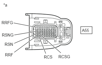
Tester Connection Condition Specified Condition A55-28 (RRF) - Body ground Ignition switch ON Below 1 V A55-1 (RRFG) - Body ground Ignition switch ON Below 1 V A55-19 (RSN) - Body ground Ignition switch ON Below 1 V A55-10 (RSNG) - Body ground Ignition switch ON Below 1 V A55-29 (RCS) - Body ground Ignition switch ON Below 1 V A55-20 (RCSG) - Body ground Ignition switch ON Below 1 V *a Front view of wire harness connector
(to Inverter with Converter Assembly)NOTE:Turning the ignition switch to ON with the inverter with converter assembly disconnected causes other DTCs to be stored. Clear the DTCs after performing this inspection.
- Turn the ignition switch off.
- Disconnect the cable from the negative (-) auxiliary battery terminal and wait for 2 minutes or more.
- Reconnect the A55 inverter with converter assembly connector.
Result
Proceed to OK NG
Result:
NG
REPAIR OR REPLACE HARNESS OR CONNECTOR
Result:
OK
See step 2
- Check that the service plug grip is not installed.
- CHECK REAR MOTOR RESOLVER WARNING:
Be sure to wear insulated gloves.
- Check that the service plug grip is not installed.NOTE:
After removing the service plug grip, do not turn the ignition switch to ON (READY), unless instructed by the repair information because this may cause a malfunction.
- Disconnect the A55 inverter with converter assembly connector.
- Measure the resistance according to the value(s) in the table below.
Standard Resistance
Tester Connection Condition Specified Condition A55-28 (RRF) - A55-1 (RRFG) Ignition switch off 9.2 to 15.2 Ω A55-19 (RSN) - A55-10 (RSNG) Ignition switch off 16.5 to 28.5 Ω A55-29 (RCS) - A55-20 (RCSG) Ignition switch off 18.4 to 30.4 Ω HINT:
To correct the variation of the measured resistance due to temperature, use the following formula to calculate the resistance at 20°C (68°F).
R20 = Rt / {1 + 0.00393 X (T - 20)}
The calculation is based on the following:
R20: Resistance at 20°C (68°F) (mΩ)
Rt: Measured resistance (mΩ)
T: Temperature when the resistance is measured (°C (°F).)
Standard Resistance (Check for Short)
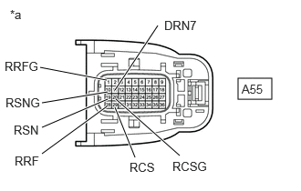
Tester Connection Condition Specified Condition A55-28 (RRF) or A55-1 (RRFG) - Body ground and other terminals Ignition switch off 1 MΩ or higher A55-19 (RSN) or A55-10 (RSNG) - Body ground and other terminals Ignition switch off 1 MΩ or higher A55-29 (RCS) or A55-20 (RCSG) - Body ground and other terminals Ignition switch off 1 MΩ or higher A55-11 (DRN7) - Body ground Ignition switch off 1 MΩ or higher *a Front view of wire harness connector
(to Inverter with Converter Assembly) - Reconnect the A55 inverter with converter assembly connector.
Result
Proceed to OK NG
Result:
OK
REAR MOTOR RESOLVER CIRCUIT NORMAL (PERFORM NEXT STEP FOR REFERENCED DTC)
Result:
NG
See step 3
- Check that the service plug grip is not installed.
- CHECK CONNECTOR CONNECTION CONDITION (REAR MOTOR RESOLVER CONNECTOR)
- Remove the rear suspension member sub-assembly.
Refer to REMOVAL [12/2019 - 10/2022] , or refer to REMOVAL [10/2022 - 11/2023]
- Check the connection condition of the rear motor resolver connector and the contact pressure of each terminal. Check the terminals for deformation, and check the connector for water ingress and foreign matter.
Refer to ELECTRONIC CIRCUIT INSPECTION PROCEDURE [12/2019 - ]
OK
- The connector is connected securely.
- The terminals are not deformed and are connected securely.
- No water or foreign matter in the connector.
Result
Result Proceed to OK A NG (The connector is not connected securely.) B NG (The terminals are not making secure contact or are deformed, or water or foreign matter exists in the connector.) C
Result:
B
CONNECT SECURELY
Result:
C
REPAIR OR REPLACE HARNESS OR CONNECTOR
Result:
A
See step 4
- Remove the rear suspension member sub-assembly.
- INSPECT REAR TRACTION MOTOR WITH TRANSAXLE ASSEMBLY (REAR MOTOR RESOLVER) WARNING:
Be sure to wear insulated gloves.
- Check that the service plug grip is not installed.NOTE:
After removing the service plug grip, do not turn the ignition switch to ON (READY), unless instructed by the repair information because this may cause a malfunction.
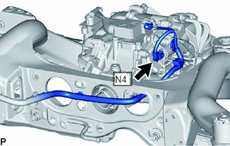
- Disconnect the N4 resolver connector.
- Measure the resistance according to the value(s) in the table below.
Standard Resistance
Tester Connection Condition Specified Condition N4-4 (RRF) - N4-6 (RRFG) Ignition switch off 8.8 to 14.8 Ω N4-3 (RSN) - N4-7 (RSNG) Ignition switch off 16.1 to 28.1 Ω N4-2 (RCS) - N4-8 (RCSG) Ignition switch off 18.0 to 30.0 Ω HINT:
To correct the variation of the measured resistance due to temperature, use the following formula to calculate the resistance at 20°C (68°F).
R20 = Rt / {1 + 0.00393 X (T - 20)}
The calculation is based on the following:
R20: Resistance at 20°C (68°F) (mΩ)
Rt: Measured resistance (mΩ)
T: Temperature when the resistance is measured (°C (°F).)
Standard Resistance (Check for Short)
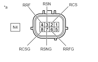
Tester Connection Condition Specified Condition N4-4 (RRF) - Body ground and other terminals (except N4-6 (RRFG)) Ignition switch off 1 MΩ or higher N4-6 (RRFG) - Body ground and other terminals (except N4-4 (RRF)) Ignition switch off 1 MΩ or higher N4-3 (RSN) - Body ground and other terminals (except N4-7 (RSNG)) Ignition switch off 1 MΩ or higher N4-7 (RSNG) - Body ground and other terminals (except N4-3 (RSN)) Ignition switch off 1 MΩ or higher N4-2 (RCS) - Body ground and other terminals (except N4-8 (RCSG)) Ignition switch off 1 MΩ or higher N4-8 (RCSG) - Body ground and other terminals (except N4-2 (RCS)) Ignition switch off 1 MΩ or higher *a Component without harness connected
(Rear Motor Resolver (Rear Traction Motor with Transaxle Assembly)) - Reconnect the N4 resolver connector.
Result
Proceed to OK NG
Result:
OK
REPAIR OR REPLACE HARNESS OR CONNECTOR
Result:
NG
REPLACE REAR TRACTION MOTOR WITH TRANSAXLE ASSEMBLY. Refer to REMOVAL [12/2019 - 10/2022] , or refer to REMOVAL [10/2022 - 11/2023]
- Check that the service plug grip is not installed.