HV Battery High-voltage Line Circuit [12/2019 - 11/2023]: Procedure
- CHECK INVERTER WITH CONVERTER ASSEMBLY (HV FLOOR UNDER WIRE CONNECTION CONDITION) WARNING:
Be sure to wear insulated gloves.
- Check that the service plug grip is not installed.NOTE:
After removing the service plug grip, do not turn the ignition switch to ON (READY), unless instructed by the repair information because this may cause a malfunction.
- Check that the bolts for the HV floor under wire is tightened to the specified torque, the HV floor under wire is connected securely, and there are no contact problems.
Specified Condition
T = 8.0 N*m (82 kgf*cm, 71 in.*lbf)
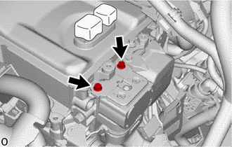
- Disconnect the HV floor under wire from the inverter with converter assembly.
- Check for arc marks on the terminals for the HV floor under wire and inverter with converter assembly.
Result
Result Proceed to The terminals are connected securely and there are no contact problems. There are no arc marks. A The terminals are not connected securely and there is a contact problem. There are arc marks. B The terminals are not connected securely and there is a contact problem. There are no arc marks. C The terminals are connected securely and there are no contact problems. There are arc marks. B - Reconnect the HV floor under wire.
Result:
B
REPLACE MALFUNCTIONING PARTS
Result:
C
CONNECT SECURELY
Result:
A
See step 2
- Check that the service plug grip is not installed.
- CHECK SERVICE PLUG GRIP (CONNECTION CONDITION) WARNING:
Be sure to wear insulated gloves.
- Visually check the connection of the service plug grip to the HV battery. Remove the service plug grip and check for contamination.
OK
Dirt or foreign matter has not entered the connectors, and there is no evidence of contamination.
- Install the service plug grip.
Result
Proceed to OK NG
Result:
NG
REPLACE SERVICE PLUG GRIP
Refer to REMOVAL [12/2019 - 10/2022] , or refer to REMOVAL [10/2022 - 11/2023]
Result:
OK
See step 3
- Visually check the connection of the service plug grip to the HV battery. Remove the service plug grip and check for contamination.
- INSPECT SERVICE PLUG GRIP WARNING:
Be sure to wear insulated gloves.
- Remove the service plug grip.
Refer to REMOVAL [12/2019 - 10/2022] , or refer to REMOVAL [10/2022 - 11/2023]
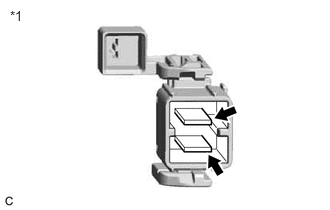
- Measure the resistance according to the value(s) in the table below.
*1 Service Plug Grip Standard Resistance
Tester Connection Condition Specified Condition Service plug grip terminals Always Below 1 Ω - Install the service plug grip.
Result
Proceed to OK NG
Result:
NG
REPLACE SERVICE PLUG GRIP
Refer to REMOVAL [12/2019 - 10/2022] , or refer to REMOVAL [10/2022 - 11/2023]
Result:
OK
See step 4
- Remove the service plug grip.
- CHECK HYBRID BATTERY TERMINAL BLOCK WARNING:
Be sure to wear insulated gloves and protective goggles.
- Remove the Hybrid battery terminal block.
Refer to REMOVAL [12/2019 - 10/2022] , or refer to REMOVAL [10/2022 - 11/2023]
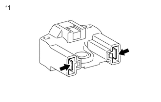
- Measure the resistance according to the value(s) in the table below.
Standard Resistance
Tester Connection Condition Specified Condition Hybrid battery terminal block Always Below 1 Ω *1 Hybrid Battery Terminal Block - Install the Hybrid battery terminal block.
Result
Proceed to OK NG
Result:
NG
REPLACE HYBRID BATTERY TERMINAL BLOCK
Refer to REMOVAL [12/2019 - 10/2022] , or refer to REMOVAL [10/2022 - 11/2023]
Result:
OK
See step 5
- Remove the Hybrid battery terminal block.
- CHECK HV BATTERY JUNCTION BLOCK ASSEMBLY (HV FLOOR UNDER WIRE CONNECTION CONDITION) WARNING:
Be sure to wear insulated gloves.
- Check that the service plug grip is not installed.NOTE:
After removing the service plug grip, do not turn the ignition switch to ON (READY), unless instructed by the repair information because this may cause a malfunction.
- Remove the No. 10 HV battery shield panel.
Refer to REMOVAL [12/2019 - 10/2022] , or refer to REMOVAL [10/2022 - 11/2023]
- Check that the HV floor under wire is connected securely, and there are no contact problems.
- Disconnect the HV floor under wire connectors from the HV battery junction block assembly.
- Check for arc marks on the terminals of the HV floor under wire and the HV battery junction block assembly.
Result
Result Proceed to The terminals are connected securely and there are no contact problems. There are no arc marks. A The terminals are not connected securely and there is a contact problem. There are arc marks. B The terminals are not connected securely and there is a contact problem. There are no arc marks. C The terminals are connected securely and there are no contact problems. There are arc marks. B - Reconnect the HV floor under wire.
- Install the No. 10 HV battery shield panel.
Result:
B
REPLACE MALFUNCTIONING PARTS
Result:
C
CONNECT SECURELY
Result:
A
See step 6
- Check that the service plug grip is not installed.
- CHECK FLOOR UNDER WIRE WARNING:
Be sure to wear insulated gloves.
- Check that the service plug grip is not installed.NOTE:
After removing the service plug grip, do not turn the ignition switch to ON (READY), unless instructed by the repair information because this may cause a malfunction.
- Remove the No. 10 HV battery shield panel.
Refer to REMOVAL [12/2019 - 10/2022] , or refer to REMOVAL [10/2022 - 11/2023]
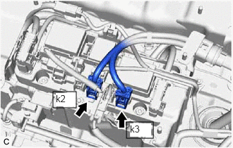
- Disconnect the HV floor under wire connectors from the HV battery junction block assembly.
- Disconnect the HV floor under wire connector from the inverter with converter assembly.
- Measure the resistance according to the value(s) in the table below.
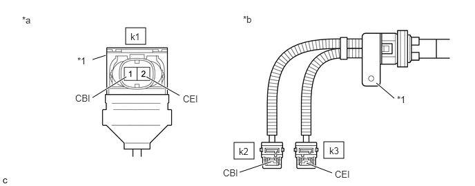
*1 Shield Ground - - *a HV Floor Under Wire
(Inverter with Converter Assembly Side)*b HV Floor Under Wire
(HV Battery Junction Block Assembly Side)Standard Resistance
Tester Connection Condition Specified Condition k1-1 (CBI) - k2-1 (CBI) Ignition switch off Below 1 Ω k1-2 (CEI) - k3-1 (CEI) Ignition switch off Below 1 Ω NOTE:Be sure not to damage or deform the terminal being inspected.
- Using a megohmmeter set to 500 V, measure the resistance according to the value(s) in the table below.NOTE:
Be sure to set the megohmmeter to 500 V when performing this test. Using a setting higher than 500 V can result in damage to the component being inspected.
Standard Resistance
Tester Connection Condition Specified Condition k1-1 (CBI) or k2-1 (CBI) - Body ground and shield ground Ignition switch off 10 MΩ or higher k1-2 (CEI) or k3-1 (CEI) - Body ground and shield ground Ignition switch off 10 MΩ or higher k1-1 (CBI) - k1-2 (CEI) Ignition switch off 10 MΩ or higher k2-1 (CBI) - k3-1 (CEI) Ignition switch off 10 MΩ or higher - Reconnect the HV floor under wire connector to the inverter with converter assembly.
- Reconnect the HV floor under wire connectors to the HV battery junction block assembly.
- Install the No. 10 HV battery shield panel.
Result
Proceed to OK NG
Result:
NG
REPLACE FLOOR UNDER WIRE
Refer to REMOVAL [12/2019 - 10/2022] , or refer to REMOVAL [10/2022 - 11/2023]
Result:
OK
See step 7
- Check that the service plug grip is not installed.
- INSPECT HV BATTERY JUNCTION BLOCK ASSEMBLY (SMRB) WARNING:
Be sure to wear insulated gloves.
- Check that the service plug grip is not installed.NOTE:
After removing the service plug grip, do not turn the ignition switch to ON (READY), unless instructed by the repair information because this may cause a malfunction.
- Remove the HV battery junction block assembly.
Refer to REMOVAL [12/2019 - 10/2022] , or refer to REMOVAL [10/2022 - 11/2023]
- Measure the resistance according to the value(s) in the table below.
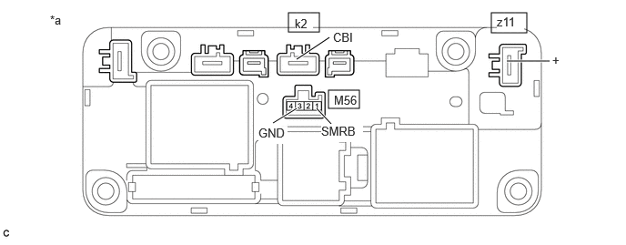
*a Component without harness connected
(HV Battery Junction Block Assembly)- - Standard Resistance
Tester Connection Condition Specified Condition z11-1 (+) - k2-1 (CBI) Auxiliary battery voltage not applied between terminals M56-1 (SMRB) and M56-3 (GND) 10 kΩ or higher z11-1 (+) - k2-1 (CBI) Auxiliary battery voltage applied between terminals M56-1 (SMRB) and M56-3 (GND) Below 1 Ω - Measure the resistance according to the value(s) in the table below.
Standard Resistance
Tester Connection Condition Specified Condition M56-1 (SMRB) - M56-3 (GND) -40 to 80°C (-40 to 176°F) 25.0 to 59.0 Ω - Install the HV battery junction block assembly.
Result
Proceed to OK NG
Result:
NG
REPLACE HV BATTERY JUNCTION BLOCK ASSEMBLY
Refer to REMOVAL [12/2019 - 10/2022] , or refer to REMOVAL [10/2022 - 11/2023]
Result:
OK
See step 8
- Check that the service plug grip is not installed.
- INSPECT HV BATTERY JUNCTION BLOCK ASSEMBLY (SMRG) WARNING:
Be sure to wear insulated gloves.
- Check that the service plug grip is not installed.NOTE:
After removing the service plug grip, do not turn the ignition switch to ON (READY), unless instructed by the repair information because this may cause a malfunction.
- Remove the HV battery junction block assembly.
Refer to REMOVAL [12/2019 - 10/2022] , or refer to REMOVAL [10/2022 - 11/2023]
- Measure the resistance according to the value(s) in the table below.
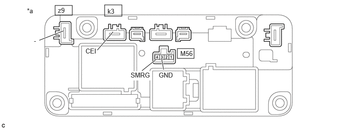
*a Component without harness connected
(HV Battery Junction Block Assembly)- - Standard Resistance
Tester Connection Condition Specified Condition z9-1 (-) - k3-1 (CEI) Auxiliary battery voltage not applied between terminals M56-4 (SMRG) and M56-3 (GND) 10 kΩ or higher z9-1 (-) - k3-1 (CEI) Auxiliary battery voltage applied between terminals M56-4 (SMRG) and M56-3 (GND) Below 1 Ω - Measure the resistance according to the value(s) in the table below.
Standard Resistance
Tester Connection Condition Specified Condition M56-4 (SMRG) - M56-3 (GND) -40 to 80°C (-40 to 176°F) 25.0 to 59.0 Ω - Install the HV battery junction block assembly.
Result
Proceed to OK NG
Result:
OK
HV BATTERY HIGH-VOLTAGE LINE CIRCUIT NORMAL (PERFORM NEXT STEP FOR REFERENCED DTC)
Result:
NG
REPLACE HV BATTERY JUNCTION BLOCK ASSEMBLY
Refer to REMOVAL [12/2019 - 10/2022] , or refer to REMOVAL [10/2022 - 11/2023]
- Check that the service plug grip is not installed.