DTC P0560-14: System Voltage (BATT) Circuit Short to Ground or Open [12/2019 - 11/2023]: Procedure
- CHECK CONNECTOR CONNECTION CONDITION (HYBRID VEHICLE CONTROL ECU CONNECTOR)
- Check the connector connections and contact pressure of the relevant terminals for the hybrid vehicle control ECU connectors.
Refer to ELECTRONIC CIRCUIT INSPECTION PROCEDURE [12/2019 - ]
OK
The connectors are connected securely and there are no contact pressure problems.
Result
Proceed to OK NG
Result:
NG
CONNECT SECURELY
Result:
OK
See step 2
- Check the connector connections and contact pressure of the relevant terminals for the hybrid vehicle control ECU connectors.
- CHECK HARNESS AND CONNECTOR (POWER SOURCE OF HYBRID VEHICLE CONTROL ECU)
- Turn the ignition switch off.
- Measure the voltage according to the value(s) in the table below.
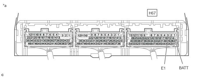
*a Component with harness connected
(Hybrid Vehicle Control ECU)- - Standard Voltage
Tester Connection Condition Specified Condition H67-27 (BATT) - H67-3 (E1) Ignition switch off 11 to 14 V Result
Proceed to OK NG
Result:
OK
REPLACE HYBRID VEHICLE CONTROL ECU. Refer to REMOVAL [12/2019 - 10/2022] , or refer to REMOVAL [10/2022 - 11/2023]
Result:
NG
See step 3
- CHECK FUSE (ECU-B NO. 2)
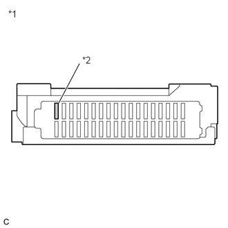
- Remove the ECU-B NO. 2 fuse from the instrument panel junction block assembly.
*1 Instrument Panel Junction Block Assembly *2 ECU-B NO. 2 Fuse - Check if there is an open circuit in the ECU-B NO. 2 fuse in the instrument panel junction block assembly.
OK
There is no open circuit in the ECU-B NO. 2 fuse.
- Install the ECU-B NO. 2 fuse.
Result
Proceed to OK NG
Result:
NG
REPLACE FUSE (ECU-B NO. 2)
Result:
OK
See step 4
- Remove the ECU-B NO. 2 fuse from the instrument panel junction block assembly.
- CHECK HARNESS AND CONNECTOR (ECU-B NO. 2 FUSE - AUXILIARY BATTERY TERMINAL)
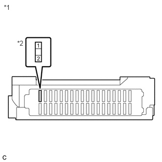
- Remove the ECU-B NO. 2 fuse from the instrument panel junction block assembly.
*1 Instrument Panel Junction Block Assembly *2 ECU-B NO. 2 Fuse Holder - Disconnect the cable from the negative (-) auxiliary battery terminal.
- Disconnect the cable from the positive (+) auxiliary battery terminal.
- Measure the resistance according to the value(s) in the table below.
Standard Resistance
Tester Connection Condition Specified Condition 1 (ECU-B NO. 2 fuse holder) - Auxiliary battery positive (+) cable Ignition switch off Below 1 Ω 1 (ECU-B NO. 2 fuse holder) - Body ground Ignition switch off 10 kΩ or higher - Connect the cable to the positive (+) auxiliary battery terminal.
- Connect the cable to the negative (-) auxiliary battery terminal.
- Install the ECU-B NO. 2 fuse.
Result
Proceed to OK NG
Result:
NG
REPAIR OR REPLACE HARNESS OR CONNECTOR
Result:
OK
See step 5
- Remove the ECU-B NO. 2 fuse from the instrument panel junction block assembly.
- CHECK HARNESS AND CONNECTOR (ECU-B NO. 2 FUSE - HYBRID VEHICLE CONTROL ECU)
- Remove the ECU-B NO. 2 fuse from the instrument panel junction block assembly.
- Disconnect the H67 hybrid vehicle control ECU connector.
- Measure the resistance according to the value(s) in the table below.
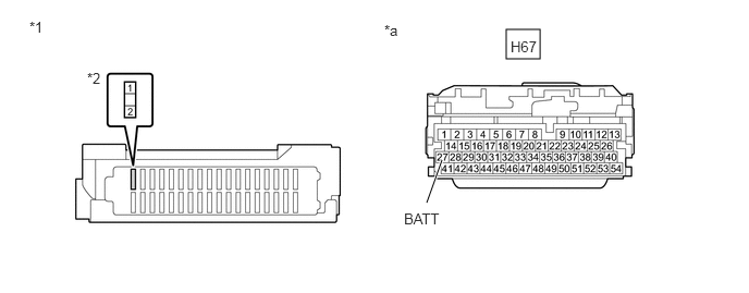
*1 Instrument Panel Junction Block Assembly *2 ECU-B NO. 2 Fuse Holder *a Front view of wire harness connector
(to Hybrid Vehicle Control ECU)- - Standard Resistance (Check for Open)
Tester Connection Condition Specified Condition 2 (ECU-B NO. 2 fuse holder) - H67-27 (BATT) Ignition switch off Below 1 Ω Standard Resistance (Check for Short)
Tester Connection Condition Specified Condition 2 (ECU-B NO. 2 fuse holder) or H67-27 (BATT) - Body ground and other terminals Ignition switch off 10 kΩ or higher - Reconnect the H67 hybrid vehicle control ECU connector.
- Reinstall the ECU-B NO. 2 fuse.
Result
Proceed to OK NG
Result:
OK
REPLACE HYBRID VEHICLE CONTROL ECU. Refer to REMOVAL [12/2019 - 10/2022] , or refer to REMOVAL [10/2022 - 11/2023]
Result:
NG
REPAIR OR REPLACE HARNESS OR CONNECTOR