Buzzer does not Sound [11/2023 - ]: Procedure
- READ VALUE USING GTS
- Connect the GTS to the DLC3.
- Turn the ignition switch to ON.
- Turn the GTS on.
- Enter the following menus: Body Electrical / Blind Spot Monitor A / Data List.
- Read the Data List according to the display on the GTS.
Body Electrical > Blind Spot Monitor "A" > Data List
Tester Display Measurement Item Range Normal Condition Diagnostic Note Clearance Warning Buzzer Support Status of clearance warning buzzer support Pending, Not Support or Support Not Support: No. 2 clearance warning buzzer support not available
Support: No. 2 clearance warning buzzer support available- Body Electrical > Blind Spot Monitor "A" > Data List
Tester Display Clearance Warning Buzzer Support Result
Result Proceed to "Not Support" is displayed. A "Support" is displayed. B
Result:
B
GO TO INTUITIVE PARKING ASSIST SYSTEM. Refer to HOW TO PROCEED WITH TROUBLESHOOTING [11/2023 - ]
Result:
A
See step 2
- PERFORM ACTIVE TEST USING GTS
- Check that the buzzer operates by performing the Active Test.
Body Electrical > Blind Spot Monitor "A" > Active Test
Tester Display Measurement Item Control Range Diagnostic Note RCTA Buzzer Sound RCTA buzzer (blind spot monitor buzzer) Stop or Start Confirm that the vehicle is stopped and the ignition switch is ON Body Electrical > Blind Spot Monitor "A" > Active Test
Tester Display RCTA Buzzer Sound OK
The RCTA buzzer (blind spot monitor buzzer) sounds.
Result
Proceed to OK NG
Result:
OK
PROCEED TO NEXT SUSPECTED AREA SHOWN IN PROBLEM SYMPTOMS TABLE. Refer to PROBLEM SYMPTOMS TABLE [11/2023 - ]
Result:
NG
See step 3
- Check that the buzzer operates by performing the Active Test.
- CHECK FOR DTC
- According to the display on the GTS, check for DTCs.
Body Electrical > Blind Spot Monitor "A" > Clear DTCs
- According to the display on the GTS, check for DTCs.
Body Electrical > Blind Spot Monitor "A" > Trouble Codes
OK
No DTCs are output.
Result
Proceed to OK NG
Result:
NG
GO TO DIAGNOSTIC TROUBLE CODE CHART. Refer to DIAGNOSTIC TROUBLE CODE CHART [11/2023 - ]
Result:
OK
See step 4
- According to the display on the GTS, check for DTCs.
- CHECK HARNESS AND CONNECTOR (RCTA BUZZER [BLIND SPOT MONITOR BUZZER] - BLIND SPOT MONITOR SENSOR RH [A])
- Disconnect the M45 RCTA buzzer (blind spot monitor buzzer) connector.
- Disconnect the M2 blind spot monitor sensor RH (A) connector.
- Measure the resistance according to the value(s) in the table below.
Standard Resistance
Tester Connection Condition Specified Condition M45-2 (BZN) - M2-3 (BUZ) Always Below 1 Ω M45-2 (BZN) or M2-3 (BUZ) - Body ground Always 10 kΩ or higher Result
Proceed to OK NG
Result:
NG
REPAIR OR REPLACE HARNESS OR CONNECTOR
Result:
OK
See step 5
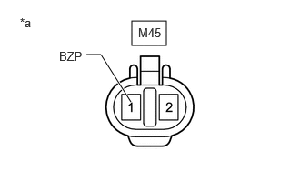
- CHECK HARNESS AND CONNECTOR (RCTA BUZZER [BLIND SPOT MONITOR BUZZER] - AUXILIARY BATTERY)
- Disconnect the RCTA buzzer (blind spot monitor buzzer) connector.
*a Front view of wire harness connector
(to RCTA Buzzer [Blind Spot Monitor Buzzer]) - Measure the voltage according to the value(s) in the table below.
Standard Voltage
Tester Connection Switch Condition Specified Condition M45-1 (BZP) - Body ground Ignition switch ON 11 to 14 V M45-1 (BZP) - Body ground Ignition switch off Below 1 V Result
Proceed to OK NG
Result:
NG
REPAIR OR REPLACE HARNESS OR CONNECTOR
Result:
OK
See step 6
- Disconnect the RCTA buzzer (blind spot monitor buzzer) connector.
- CHECK RCTA BUZZER (BLIND SPOT MONITOR BUZZER)
- Replace the RCTA buzzer (blind spot monitor buzzer) with a new or known good one and check if the same malfunction recurs.
Refer to REMOVAL [12/2019 - ]
OK
Malfunction does not reoccur (returns to normal).
Result
Proceed to OK NG
Result:
OK
END (RCTA BUZZER [BLIND SPOT MONITOR BUZZER] WAS DEFECTIVE)
Result:
NG
REPLACE BLIND SPOT MONITOR SENSOR RH (A). Refer to REMOVAL [11/2023 - ]
- Replace the RCTA buzzer (blind spot monitor buzzer) with a new or known good one and check if the same malfunction recurs.