DTC B142A-88: Servo Motor LIN Communication Bus off [11/2023 - ]: Procedure
- PERFORM ACTIVE TEST USING GTS
- Perform the Active Test according to the display on the GTS.
Body Electrical > Air Conditioner > Active Test
Tester Display Measurement Item Control Range Diagnostic Note Front Left Air Mix Damper Control Servo Motor This test activates the front left air mix damper control servo motor.
(No. 1 air conditioning radiator damper servo sub-assembly (front left side air mix))128: Min
384: MaxOperate with the ignition switch ON. Front Right Air Mix Damper Control Servo Motor This test activates the front right air mix damper control servo motor.
(No. 1 air conditioning radiator damper servo sub-assembly (front right side air mix))128: Min
384: MaxOperate with the ignition switch ON. Air Inlet Damper Control Servo Motor This test activates the air inlet damper control servo motor.
(No. 1 blower damper servo sub-assembly)128: Min
384: MaxOperate with the ignition switch ON. Front Air Outlet Damper Control Servo Motor This test activates the front air outlet damper control servo motor.
(No. 1 air conditioning radiator damper servo sub-assembly (front mode))128: Min
384: MaxOperate with the ignition switch ON. Body Electrical > Air Conditioner > Active Test
Tester Display Front Left Air Mix Damper Control Servo Motor Body Electrical > Air Conditioner > Active Test
Tester Display Front Right Air Mix Damper Control Servo Motor Body Electrical > Air Conditioner > Active Test
Tester Display Air Inlet Damper Control Servo Motor Body Electrical > Air Conditioner > Active Test
Tester Display Front Air Outlet Damper Control Servo Motor Result
Result Proceed to All of the damper servo motors do not operate A Any of the damper servo motors does not operate B All of the damper servo motors operate C
Result:
B
REPLACE AIR CONDITIONING HARNESS ASSEMBLY
Refer to DISASSEMBLY [10/2022 - ]
Result:
C
REPLACE AIR CONDITIONING AMPLIFIER ASSEMBLY
Refer to REMOVAL [11/2023 - ]
Result:
A
See step 2
- Perform the Active Test according to the display on the GTS.
- CHECK AIR CONDITIONING AMPLIFIER ASSEMBLY NOTE:
When inspecting the air conditioning amplifier assembly, be careful not to cause a short.
Pre-procedure1
- Disconnect the z18 air conditioning amplifier assembly connector.
Procedure1
- Measure the resistance according to the value(s) in the table below.
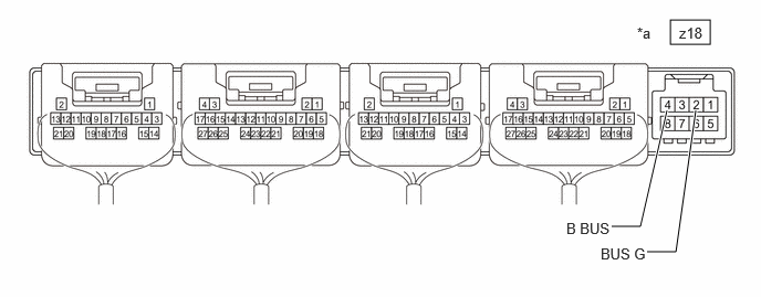
*a Component without harness connected
(Air Conditioning Amplifier Assembly)- - Standard Resistance
Tester Connection Condition Specified Condition z18-2 (BUS G) - Body ground Always Below 1 Ω - Measure the voltage according to the value(s) in the table below.
Standard Voltage
Tester Connection Condition Specified Condition z18-4 (B BUS) - z18-2 (BUS G) Ignition switch off 11 to 14 V Result
Proceed to OK NG Post-procedure1
- None
Result:
NG
REPLACE AIR CONDITIONING AMPLIFIER ASSEMBLY
Refer to REMOVAL [11/2023 - ]
Result:
OK
See step 3
- Disconnect the z18 air conditioning amplifier assembly connector.
- CHECK AIR CONDITIONING AMPLIFIER ASSEMBLY NOTE:
When inspecting the air conditioning amplifier assembly, be careful not to cause a short.
Pre-procedure1
- Disconnect the z18 air conditioning amplifier assembly connector.
Procedure1
- Using an oscilloscope, check the waveform.
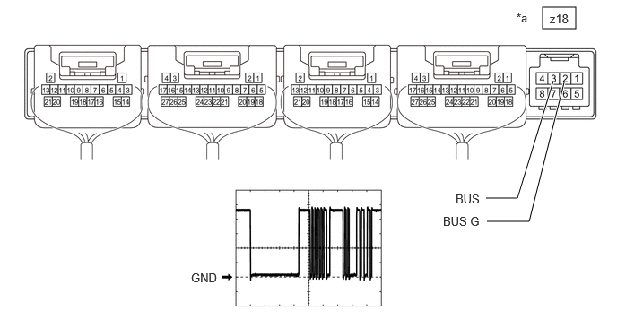
*a Component without harness connected
(Air Conditioning Amplifier Assembly)- - Item Content Tester Connection z18-3 (BUS) - z18-2 (BUS G) Tool Setting 2 V/DIV., 20 μs/DIV. Condition Ignition switch ON OK
The waveform displays properly.
Result
Proceed to OK NG Post-procedure1
- None
Result:
OK
REPLACE AIR CONDITIONING HARNESS ASSEMBLY
Refer to DISASSEMBLY [10/2022 - ]
Result:
NG
REPLACE AIR CONDITIONING AMPLIFIER ASSEMBLY
Refer to REMOVAL [11/2023 - ]
- Disconnect the z18 air conditioning amplifier assembly connector.