DTC B143B-7F: Air Inlet Damper Control Servo Motor Actuator Stuck Off [11/2023 - ]: Procedure
- CHECK NO. 1 BLOWER DAMPER SERVO SUB-ASSEMBLY (INSTALLATION CONDITION)
- Check that the No. 1 blower damper servo sub-assembly is installed correctly.
HINT:
Refer to REASSEMBLY [12/2019 - ]
OK
No. 1 blower damper servo sub-assembly is installed correctly.
Result
Proceed to OK NG
Result:
NG
REINSTALL NO. 1 BLOWER DAMPER SERVO SUB-ASSEMBLY
Refer to REASSEMBLY [12/2019 - ]
Result:
OK
See step 2
- Check that the No. 1 blower damper servo sub-assembly is installed correctly.
- CHECK NO. 1 BLOWER DAMPER SERVO SUB-ASSEMBLY (MOTOR, LINK, DAMPER)
- Check for a wire harness caught between the links of the motors and dampers.
OK
No wire harnesses are caught between the links of the motors and dampers.
Result
Proceed to OK NG
Result:
NG
REMOVE PINCHED WIRE HARNESS
Result:
OK
See step 3
- Check for a wire harness caught between the links of the motors and dampers.
- PERFORM ACTIVE TEST USING GTS
- Perform the Active Test according to the display on the GTS.
Body Electrical > Air Conditioner > Active Test
Tester Display Measurement Item Control Range Diagnostic Note Air Inlet Damper Control Servo Motor This test activates the air inlet damper control servo motor.
(No. 1 blower damper servo sub-assembly)128: Min
384: MaxOperate with the ignition switch ON. Body Electrical > Air Conditioner > Data List
Tester Display Measurement Item Range Normal Condition Inspection Item Air Inlet Damper Control Servo Motor Actual Pulse No. 1 blower damper servo sub-assembly actual pulse 128 to 384 - Fresh: 220 (pulse)
- Recirculation: 256 (pulse)
No. 1 blower damper servo sub-assembly circuit malfunction Body Electrical > Air Conditioner > Active Test
Active Test Display Air Inlet Damper Control Servo Motor Data List Display Air Inlet Damper Control Servo Motor Actual Pulse OK
The value of the Data List changes in accordance with the operation of the Active Test.
Result
Proceed to OK NG
Result:
NG
See step 8
Result:
OK
See step 4
- Perform the Active Test according to the display on the GTS.
- PERFORM ACTIVE TEST USING GTS
- Perform the Active Test according to the display on the GTS.
Body Electrical > Air Conditioner > Active Test
Tester Display Measurement Item Control Range Diagnostic Note Air Inlet Damper Control Servo Motor This test activates the air inlet damper control servo motor.
(No. 1 blower damper servo sub-assembly)128: Min
384: MaxOperate with the ignition switch ON. Body Electrical > Air Conditioner > Data List
Tester Display Measurement Item Range Normal Condition Inspection Item Air Inlet Damper Control Servo Motor Target Pulse No. 1 blower damper servo sub-assembly target pulse 128 to 384 - Fresh: 220 (pulse)
- Recirculation: 256 (pulse)
No. 1 blower damper servo sub-assembly circuit malfunction Air Inlet Damper Control Servo Motor Actual Pulse No. 1 blower damper servo sub-assembly actual pulse 128 to 384 - Fresh: 220 (pulse)
- Recirculation: 256 (pulse)
No. 1 blower damper servo sub-assembly circuit malfunction Body Electrical > Air Conditioner > Active Test
Active Test Display Air Inlet Damper Control Servo Motor Data List Display Air Inlet Damper Control Servo Motor Target Pulse Air Inlet Damper Control Servo Motor Actual Pulse OK
The target pulse value of the Data List matches the actual pulse.
Result
Proceed to OK NG
Result:
OK
USE SIMULATION METHOD TO CHECK
Refer to HOW TO PROCEED WITH TROUBLESHOOTING [12/2019 - ]
Result:
NG
See step 5
- Perform the Active Test according to the display on the GTS.
- INSPECT AIR CONDITIONING HARNESS ASSEMBLY
Pre-procedure1
- Disconnect the A No. 1 air conditioning radiator damper servo sub-assembly connector.
- Disconnect the B No. 1 blower damper servo sub-assembly connector.
Procedure1
- Measure the resistance according to the value(s) in the table below.
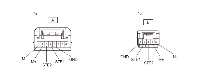
*a Front view of wire harness connector
(to No. 1 Air Conditioning Radiator Damper Servo Sub-assembly)*b Front view of wire harness connector
(to No. 1 Blower Damper Servo Sub-assembly)Standard Resistance
Tester Connection Condition Specified Condition A-1 (M-) - B-5 (M-) Always Below 1 Ω A-2 (M+) - B-4 (M+) Always Below 1 Ω A-3 (STE2) - B-3 (STE2) Always Below 1 Ω A-4 (STE1) - B-2 (STE1) Always Below 1 Ω A-5 (GND) - B-1 (GND) Always Below 1 Ω A-1 (M-) or B-5 (M-) - Other terminals and body ground Always 10 kΩ or higher A-2 (M+) or B-4 (M+) - Other terminals and body ground Always 10 kΩ or higher A-3 (STE2) or B-3 (STE2) - Other terminals and body ground Always 10 kΩ or higher A-4 (STE1) or B-2 (STE1) - Other terminals and body ground Always 10 kΩ or higher Result
Proceed to OK NG Post-procedure1
- None
Result:
NG
REPAIR AIR CONDITIONING HARNESS ASSEMBLY
Refer to DISASSEMBLY [10/2022 - ]
Result:
OK
See step 6
- REPLACE NO. 1 BLOWER DAMPER SERVO SUB-ASSEMBLY
HINT:
Refer to DISASSEMBLY [12/2019 - ]
Result
Proceed to NEXT Result:
NEXT
See step 7
- PERFORM ACTIVE TEST USING GTS
- Perform the Active Test according to the display on the GTS.
Body Electrical > Air Conditioner > Active Test
Tester Display Measurement Item Control Range Diagnostic Note Air Inlet Damper Control Servo Motor This test activates the air inlet damper control servo motor.
(No. 1 blower damper servo sub-assembly)128: Min
384: MaxOperate with the ignition switch ON. Body Electrical > Air Conditioner > Data List
Tester Display Measurement Item Range Normal Condition Inspection Item Air Inlet Damper Control Servo Motor Actual Pulse No. 1 blower damper servo sub-assembly actual pulse 128 to 384 - Fresh: 220 (pulse)
- Recirculation: 256 (pulse)
No. 1 blower damper servo sub-assembly circuit malfunction Body Electrical > Air Conditioner > Active Test
Active Test Display Air Inlet Damper Control Servo Motor Data List Display Air Inlet Damper Control Servo Motor Actual Pulse OK
The value of the Data List changes in accordance with the operation of the Active Test.
Result
Proceed to OK NG
Result:
OK
END
Result:
NG
REPAIR AIR CONDITIONING HARNESS ASSEMBLY
Refer to DISASSEMBLY [10/2022 - ]
- Perform the Active Test according to the display on the GTS.
- PERFORM ACTIVE TEST USING GTS
- Perform the Active Test according to the display on the GTS.
Body Electrical > Air Conditioner > Active Test
Tester Display Measurement Item Control Range Diagnostic Note Front Air Outlet Damper Control Servo Motor This test activates the front air outlet damper control servo motor.
(No. 1 air conditioning radiator damper servo sub-assembly (front mode))128: Min
384: MaxOperate with the ignition switch ON. Body Electrical > Air Conditioner > Data List
Tester Display Measurement Item Range Normal Condition Inspection Item Front Air Outlet Damper Control Servo Motor Actual Pulse No. 1 air conditioning radiator damper servo sub-assembly (front mode) actual pulse 128 to 384 - FACE: 256 (pulse)
- B/L: 267 (pulse)
- FOOT-A: 288 (pulse)
- FOOT-R (F): 297 (pulse)
- FOOT-D: 305 (pulse)
- F/D-R: 320 (pulse)
- D/F: 339 (pulse)
- DEF: 348 (pulse)
No. 1 air conditioning radiator damper servo sub-assembly (front mode) circuit malfunction Body Electrical > Air Conditioner > Active Test
Active Test Display Front Air Outlet Damper Control Servo Motor Data List Display Front Air Outlet Damper Control Servo Motor Actual Pulse OK
The value of the Data List changes in accordance with the operation of the Active Test.
Result
Proceed to OK NG
Result:
OK
See step 6
Result:
NG
See step 9
- Perform the Active Test according to the display on the GTS.
- CHECK BLOWER ASSEMBLY (DAMPER)
Pre-procedure1
- Remove the No. 1 blower damper servo sub-assembly.
HINT:
Refer to DISASSEMBLY [12/2019 - ]
Procedure1
- Operate the dampers by hand.
OK
The dampers are easily operated by hand.
Result
Proceed to OK NG Post-procedure1
- None
Result:
OK
REPLACE AIR CONDITIONING AMPLIFIER ASSEMBLY
Refer to REMOVAL [11/2023 - ]
Result:
NG
REPAIR OR REPLACE BLOWER ASSEMBLY
Refer to REMOVAL [11/2023 - ]
- Remove the No. 1 blower damper servo sub-assembly.