DTC P1CCC-96: DC/DC Converter Enable Component Internal Failure [10/2021 - 11/2023]: Procedure
- CHECK DTC OUTPUT
- Check for DTCs.
Powertrain > Engine > Trouble Codes
Powertrain > Hybrid Control > Trouble Codes
Powertrain > Motor Generator > Trouble Codes
Result
Result Proceed to P1CCC-96 only is output, or DTCs except the ones in the table below are also output. A DTCs of hybrid control system in the table below are output. B DTCs of motor generator control system in the table below are output. C DTCs of SFI system in the table below are output. D TABLE 1Malfunction Content System Relevant DTC Insulation Malfunction Hybrid control system P1C7C-49 Hybrid/EV Battery Voltage System Isolation (A/C Area) Internal Electronic Failure P1C7D-49 Hybrid/EV Battery Voltage System Isolation (Hybrid/EV Battery Area) Internal Electronic Failure P1C7E-49 Hybrid/EV Battery Voltage System Isolation (Transaxle Area) Internal Electronic Failure P1C7F-49 Hybrid/EV Battery Voltage System Isolation (Direct Current Area) Internal Electronic Failure P1C80-49 Hybrid/EV Battery Voltage System Isolation (Rear Motor Area) Internal Electronic Failure High Voltage Circuit Malfunction Hybrid control system P0AA6-49 Hybrid/EV Battery Voltage System Isolation Internal Electronic Failure P0AD9-11 Hybrid/EV Battery Positive Contactor Circuit Short to Ground P0ADD-11 Hybrid/EV Battery Negative Contactor Circuit Short to Ground P0AE4-11 Hybrid/EV Battery Precharge Contactor Circuit Short to Ground P1C84-49 High Voltage Power Resource Circuit Short during Ready ON P3004-49 High Voltage Power Resource Circuit Short during Pre-Charge TABLE 2Malfunction Content System Relevant DTC System malfunction Hybrid control system P0A93-00 Inverter "A" Cooling System Performance P0C73-96 Motor Electronics Coolant Pump "A" Component Internal Failure P314A-31 Motor Electronics Coolant Pump "A" No Signal Motor generator control system P0E57-17 DC/DC Converter Voltage Sensor "A" (VL) Circuit Voltage Above Threshold SFI system P059A-71 Active Grille Air Shutter "A" Actuator Stuck P059A-79 Active Grille Air Shutter "A" Mechanical Linkage Failure P05A2-12 Active Grille Air Shutter "A" Circuit Short to Battery P15AD-87 Active Grille Air Shutter "A" Missing Message HINT:
P1CCC-96 may be output as a result of the malfunction indicated by the DTCs above.
- The chart above is listed in inspection order of priority.
- Check DTCs that are output at the same time by following the listed order. (The main cause of the malfunction can be determined without performing unnecessary inspections.)
- Turn the ignition switch off.
Result:
B
GO TO DTC CHART (HYBRID CONTROL SYSTEM)
Refer to DIAGNOSTIC TROUBLE CODE CHART [10/2021 - 11/2023]
Result:
C
GO TO DTC CHART (MOTOR GENERATOR CONTROL SYSTEM) . Refer to DIAGNOSTIC TROUBLE CODE CHART [10/2021 - 11/2023]
Result:
D
GO TO DTC CHART (SFI SYSTEM)
Refer to DIAGNOSTIC TROUBLE CODE CHART [10/2021 - 10/2022] , or refer to DIAGNOSTIC TROUBLE CODE CHART [10/2022 - 11/2023]
Result:
A
See step 2
- Check for DTCs.
- CHECK AMD TERMINAL CONNECTION CONDITION WARNING:
Be sure to wear insulated gloves.
- Check that the service plug grip is not installed.NOTE:
After removing the service plug grip, do not turn the ignition switch to ON (READY), unless instructed by the repair information because this may cause a malfunction.
- Check that the nuts for the AMD terminal are tightened to the specified torque, the AMD terminal is connected securely, and there are no contact problems.
Torque
Inverter with converter assembly side
T=10 N*m (102 kgf*cm, 7 ft.*lbf)
No. 1 engine room relay block and junction block assembly side
T=8.0 N*m (82 kgf*cm, 71 in.*lbf)
Result
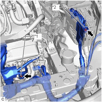
Result Proceed to There are no arc marks. The terminal is connected securely and there are no contact problems. A There are no arc marks. The terminal is not connected securely and there is a contact problem. B There are arc marks. - C *1 AMD Terminal
(Inverter with Converter Assembly Side)*2 AMD Terminal
(No. 1 Engine Room Relay Block and Junction Block Assembly Side)
Result:
B
CONNECT SECURELY
Result:
C
REPLACE MALFUNCTIONING PARTS
Result:
A
See step 3
- Check that the service plug grip is not installed.
- CHECK AMD TERMINAL VOLTAGE WARNING:
Be sure to wear insulated gloves.
- Connect the cable to the negative (-) auxiliary battery terminal.
- Measure the voltage according to the value(s) in the table below.
Standard Voltage
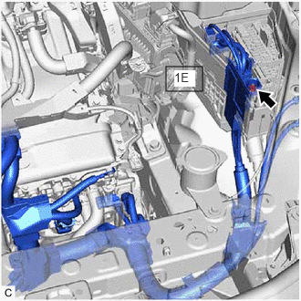
Tester Connection Condition Specified Condition 1E-1 - Body ground Ignition switch off Same as auxiliary battery voltage - Disconnect the cable from the negative (-) auxiliary battery terminal.
Result
Proceed to OK NG
Result:
NG
See step 7
Result:
OK
See step 4
- CHECK ENGINE WIRE WARNING:
Be sure to wear insulated gloves.
- Check that the service plug grip is not installed.NOTE:
After removing the service plug grip, do not turn the ignition switch to ON (READY), unless instructed by the repair information because this may cause a malfunction.
- Disconnect the engine wire from the AMD terminal (inverter with converter assembly side and No. 1 engine room relay block and junction block assembly side).
- Measure the resistance according to the value(s) in the table below.
Standard Resistance
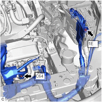
Tester Connection Condition Specified Condition C64-1 (AMD) - 1E-1 Always Below 1 Ω - Install the engine wire.
Result
Proceed to OK NG
Result:
NG
REPLACE ENGINE WIRE
Result:
OK
See step 5
- Check that the service plug grip is not installed.
- CHECK COOLING SYSTEM
Refer to Cooling System [10/2021 - 11/2023]
Result
Proceed to NEXT Result:
NEXT
See step 6
- CHECK DC/DC CONVERTER FUNCTION
HINT:
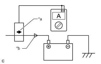
The current at the AMD terminal cannot be measured directly because of space limitations. Measure the current flowing at the auxiliary battery instead.
- Connect the AC/DC 400 A probe of the tester to the positive (+) auxiliary battery cable.
- Install the service plug grip.
- Connect the cable to the negative (-) auxiliary battery terminal.
- Turn the ignition switch to ON (READY) and leave the vehicle as it is until the electric current flowing to the auxiliary battery becomes 10 A or less.
*a Probe Direction *b Current Flowing to Auxiliary Battery HINT:
If the ignition switch turns off immediately after it is turned to ON (READY), auxiliary battery voltage may be low. Recharge the auxiliary battery and perform this procedure again.
- Measure the current flowing from the auxiliary battery with the ignition switch ON (READY), the headlight position switch and blower motor switch in the HI position, and the rear window defogger turned on.
*a Probe Direction *b Current Flowing from Auxiliary Battery Standard Current
Item Condition Specified Condition Current flowing from auxiliary battery Ignition switch ON (READY)
(The headlight position switch and blower motor switch are in the HI position, and the rear window defogger is turned on.)0 A or less
(no current from auxiliary battery) - Measure the voltage according to the value(s) in the table below.
Standard Voltage
Item Condition Specified Condition Auxiliary battery voltage Ignition switch ON (READY)
(The headlight position switch and blower motor switch are in the HI position, and the rear window defogger is turned on.)12.5 to 15 V - Turn the ignition switch off.
Result
Proceed to OK NG
Result:
OK
REPLACE INVERTER WITH CONVERTER ASSEMBLY
Refer to REMOVAL [12/2019 - 10/2022] , or refer to REMOVAL [10/2022 - 11/2023]
Result:
NG
See step 8
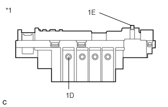
- CHECK FUSIBLE LINK BLOCK ASSEMBLY (DC/DC)
- Disconnect the cable from the negative (-) auxiliary battery terminal.
- Remove the fusible link block assembly (DC/DC).
*1 Fusible link block assembly - Measure the resistance according to the value(s) in the table below.
Standard Resistance
Tester Connection Condition Specified Condition 1E-1 - 1D-1 Always Below 1 Ω Result
Proceed to OK NG
Result:
OK
REPAIR OR REPLACE WIRE HARNESS
Result:
NG
REPLACE FUSIBLE LINK BLOCK ASSEMBLY (DC/DC)
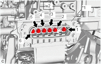
- CHECK HIGH VOLTAGE INSULATION WARNING:
Be sure to wear insulated gloves.
- Check that the service plug grip is not installed.NOTE:
After removing the service plug grip, do not turn the ignition switch to ON (READY), unless instructed by the repair information because this may cause a malfunction.
- Remove the inverter cover from the inverter with converter assembly.
- Using a megohmmeter set to 500 V, measure the insulation resistance according to the value(s) in the table below.NOTE:
Be sure to set the megohmmeter to 500 V when performing this test. Using a setting higher than 500 V can result in damage to the component being inspected.
Standard Resistance
Tester Connection Condition Specified Condition w2-1 (W) - Body ground and shield ground Ignition switch off 1 MΩ or higher w2-2 (U) - Body ground and shield ground Ignition switch off 1 MΩ or higher w2-3 (V) - Body ground and shield ground Ignition switch off 1 MΩ or higher w2-4 (W) - Body ground and shield ground Ignition switch off 1 MΩ or higher w2-5 (U) - Body ground and shield ground Ignition switch off 1 MΩ or higher w2-6 (V) - Body ground and shield ground Ignition switch off 1 MΩ or higher HINT:
Perform this inspection while the motor cable is connected.
*1 Shield Ground - Install the inverter cover to the inverter with converter assembly.
Result
Proceed to OK NG
Result:
NG
See step 10
Result:
OK
See step 9
- Check that the service plug grip is not installed.
- CHECK REAR MOTOR HIGH-VOLTAGE CIRCUIT
Refer to Rear Motor High-voltage Circuit [12/2019 - 11/2023]
HINT:
If the "Rear Motor High-voltage Circuit" inspection results are normal, perform the next step.
Result
Proceed to NEXT Result:
NEXT
REPLACE INVERTER WITH CONVERTER ASSEMBLY
Refer to REMOVAL [12/2019 - 10/2022] , or refer to REMOVAL [10/2022 - 11/2023]
- CHECK GENERATOR HIGH-VOLTAGE CIRCUIT
Refer to Generator High-voltage Circuit [12/2019 - 11/2023]
Result
Proceed to NEXT Result:
NEXT
See step 11
- CHECK MOTOR HIGH-VOLTAGE CIRCUIT
Refer to Motor High-voltage Circuit [12/2019 - 11/2023]
HINT:
If the "Motor High-voltage Circuit" inspection results are normal, perform the next step.
Result
Proceed to NEXT Result:
NEXT
REPLACE INVERTER WITH CONVERTER ASSEMBLY
Refer to REMOVAL [12/2019 - 10/2022] , or refer to REMOVAL [10/2022 - 11/2023]