DTC P3124-1F: Lost Communication between Drive Motor "A" and HV ECU Circuit Intermittent; DTC P3124-87: Lost Communication between Drive Motor "A" and HV ECU Missing Message [12/2019 - 11/2023]: Procedure
- CLEAR DTC
- Clear the DTCs.
Powertrain > Motor Generator > Clear DTCs
- Turn the ignition switch off.
Result
Proceed to NEXT
Result:
NEXT
See step 2
- Clear the DTCs.
- CHECK DIAGNOSIS RELATED INFORMATION AND DTC OUTPUT (MOTOR GENERATOR)
- Read the diagnosis related information and check for DTCs.
Powertrain > Motor Generator > Utility
Tester Display Diagnosis Related Information Powertrain > Motor Generator > Trouble Codes
Result
Result Proceed to P3124-1F or P3124-87 is listed in Diagnosis Related Information or P3124-1F or P3124-87 is output. A P3124-1F and P3124-87 are not listed in Diagnosis Information and P3124-1F and P3124-87 are not output. B - Turn the ignition switch off.
Result:
B
CHECK FOR INTERMITTENT PROBLEMS
Refer to CHECK FOR INTERMITTENT PROBLEMS [12/2019 - 11/2023]
Result:
A
See step 3
- Read the diagnosis related information and check for DTCs.
- CHECK HYBRID VEHICLE CONTROL ECU (CHECK WAVEFORM)
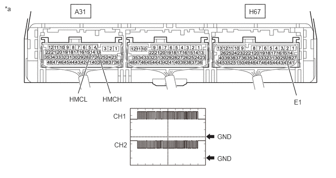
- Connect an oscilloscope between the hybrid vehicle control ECU terminals specified in the following table.
- Turn the ignition switch to ON.
- Measure the waveform.
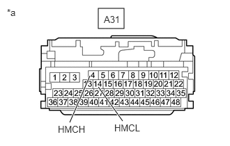
*a Component with harness connected
(Hybrid Vehicle Control ECU)- - Item Contents Tester Connection CH1: A31-4 (HMCH) - H67-3 (E1)
CH2: A31-14 (HMCL) - H67-3 (E1)Condition Ignition switch ON Result
Result Proceed to The waveform appears as shown in the illustration. A The waveform differs from the one shown in the illustration. B HINT:
- Perform this inspection with the connector connected.
- If pulses are generated, the shape of the waveform can be assumed to be normal.
- The shape of the waveform may vary according to communication conditions.
- Turn the ignition switch off.
Result:
A
REPLACE INVERTER WITH CONVERTER ASSEMBLY
Refer to REMOVAL [12/2019 - 10/2022] , or refer to REMOVAL [10/2022 - 11/2023]
Result:
B
See step 4
- CHECK CONNECTOR CONNECTION CONDITION (HYBRID VEHICLE CONTROL ECU CONNECTOR)
- Check the connector connections and contact pressure of the relevant terminals for the hybrid vehicle control ECU connectors.
Refer to ELECTRONIC CIRCUIT INSPECTION PROCEDURE [12/2019 - ]
OK
The connectors are connected securely and there are no contact pressure problems.
Result
Proceed to OK NG
Result:
NG
CONNECT SECURELY
Result:
OK
See step 5
- Check the connector connections and contact pressure of the relevant terminals for the hybrid vehicle control ECU connectors.
- CHECK CONNECTOR CONNECTION CONDITION (INVERTER WITH CONVERTER ASSEMBLY CONNECTOR) WARNING:
Be sure to wear insulated gloves.
- Check that the service plug grip is not installed.NOTE:
After removing the service plug grip, do not turn the ignition switch to ON (READY), unless instructed by the repair information because this may cause a malfunction.
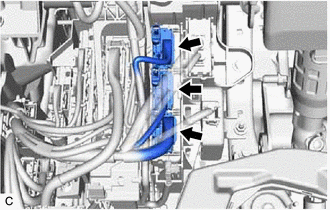
- Check the connection condition of the low voltage connectors of the inverter with converter assembly and the contact pressure of each terminal. Check the terminals for deformation, and the connector for water and foreign matter.
Refer to ELECTRONIC CIRCUIT INSPECTION PROCEDURE [12/2019 - ]
NOTE:Before disconnecting the connector, confirm that it is properly connected by checking that the claws of the lock levers are engaged and that the connector cannot be pulled off.
OK
- The connector is connected securely.
- The terminals are not deformed and are connected securely.
- No water or foreign matter in the connector.
Result
Result Proceed to OK A NG (The connector is not connected securely.) B NG (The terminals are not making secure contact or are deformed, or water or foreign matter exists in the connector.) C HINT:
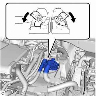
When connecting the connector, connect it with the lock levers raised. Rotate each lock lever downward and make sure that the connector is securely connected. When a lock lever is fully lowered, a click will be heard as its claw engages. After the click is heard, pull up on the connector to confirm that it is securely connected.
Result:
B
CONNECT SECURELY
Result:
C
REPAIR OR REPLACE HARNESS OR CONNECTOR
Result:
A
See step 6
- Check that the service plug grip is not installed.
- CHECK HARNESS AND CONNECTOR (HYBRID VEHICLE CONTROL ECU - INVERTER WITH CONVERTER ASSEMBLY) WARNING:
Be sure to wear insulated gloves.
- Check that the service plug grip is not installed.NOTE:
After removing the service plug grip, do not turn the ignition switch to ON (READY), unless instructed by the repair information because this may cause a malfunction.
- Disconnect the A55 inverter with converter assembly connector.
- Disconnect the A31 hybrid vehicle control ECU connector.
- Measure the resistance according to the value(s) in the table below.
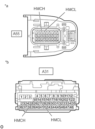
*a Front view of wire harness connector
(to Inverter with Converter Assembly)*b Front view of wire harness connector
(to Hybrid Vehicle Control ECU)Standard Resistance (Check for Open)
Tester Connection Condition Specified Condition A55-3 (HMCH) - A31-4 (HMCH) Ignition switch off Below 1 Ω A55-4 (HMCL) - A31-14 (HMCL) Ignition switch off Below 1 Ω Standard Resistance (Check for Short)
Tester Connection Condition Specified Condition A55-3 (HMCH) or A31-4 (HMCH) - Body ground and other terminals Ignition switch off 10 kΩ or higher A55-4 (HMCL) or A31-14 (HMCL) - Body ground and other terminals Ignition switch off 10 kΩ or higher - Connect the cable to the negative (-) auxiliary battery terminal.
- Turn the ignition switch to ON.
- Measure the voltage according to the value(s) in the table below.
Standard Voltage
Tester Connection Condition Specified Condition A55-3 (HMCH) or A31-4 (HMCH) - Body ground and other terminals Ignition switch ON Below 1 V A55-4 (HMCL) or A31-14 (HMCL) - Body ground and other terminals Ignition switch ON Below 1 V NOTE:Turning the ignition switch to ON with the hybrid vehicle control ECU and inverter with converter assembly connectors disconnected causes other DTCs to be stored. Clear the DTCs after performing this inspection.
- Turn the ignition switch off.
- Reconnect the A31 hybrid vehicle control ECU connector.
- Reconnect the A55 inverter with converter assembly connector.
Result
Proceed to OK NG
Result:
NG
REPAIR OR REPLACE HARNESS OR CONNECTOR
Result:
OK
See step 7
- Check that the service plug grip is not installed.
- CHECK INVERTER WITH CONVERTER ASSEMBLY
- Disconnect the A31 hybrid vehicle control ECU connector.
- Measure the resistance according to the value(s) in the table below.
*a Front view of wire harness connector
(to Hybrid Vehicle Control ECU)Standard Resistance
Tester Connection Condition Specified Condition A31-4 (HMCH) - A31-14 (HMCL) Ignition switch off 80 to 170 Ω - Reconnect the A31 hybrid vehicle control ECU connector.
Result
Proceed to OK NG
Result:
OK
REPLACE HYBRID VEHICLE CONTROL ECU
Refer to REMOVAL [12/2019 - 10/2022] , or refer to REMOVAL [10/2022 - 11/2023]
Result:
NG
REPLACE INVERTER WITH CONVERTER ASSEMBLY
Refer to REMOVAL [12/2019 - 10/2022] , or refer to REMOVAL [10/2022 - 11/2023]