DTC P0A7A-73: Generator Inverter Actuator Stuck Closed [12/2019 - 11/2023]: Procedure
- CHECK DTC OUTPUT (HYBRID CONTROL)
- Check for DTCs.
Powertrain > Hybrid Control > Trouble Codes
Result
Result Proceed to P0A7A-73 only is output, or DTCs except the ones in the table below are also output. A Any of the following DTCs are also output. B Malfunction Content Relevant DTC Insulation Malfunction P1C7C-49 Hybrid/EV Battery Voltage System Isolation (A/C Area) Internal Electronic Failure P1C7D-49 Hybrid/EV Battery Voltage System Isolation (Hybrid/EV Battery Area) Internal Electronic Failure P1C7E-49 Hybrid/EV Battery Voltage System Isolation (Transaxle Area) Internal Electronic Failure P1C7F-49 Hybrid/EV Battery Voltage System Isolation (Direct Current Area) Internal Electronic Failure P1C80-49 Hybrid/EV Battery Voltage System Isolation (Rear Motor Area) Internal Electronic Failure HINT:
- P0A7A-73 may be output as a result of the malfunctions indicated by the DTCs above.
- The chart above is listed in inspection order of priority.
- Check DTCs that are output at the same time by following the listed order. (The main cause of the malfunction can be determined without performing unnecessary inspections.)
- P0A7A-73 may be output as a result of the malfunctions indicated by the DTCs above.
- Turn the ignition switch off.
Result:
B
GO TO DTC CHART (HYBRID CONTROL SYSTEM)
Refer to DIAGNOSTIC TROUBLE CODE CHART [12/2019 - 09/2020] , or refer to DIAGNOSTIC TROUBLE CODE CHART [09/2020 - 10/2021] , or refer to DIAGNOSTIC TROUBLE CODE CHART [10/2021 - 11/2023]
Result:
A
See step 2
- Check for DTCs.
- CHECK HYBRID VEHICLE TRANSAXLE ASSEMBLY (GENERATOR (MG1))
Refer to PROCEDURE - Step 2
Result
Proceed to OK NG Result:
NG
See step 4
Result:
OK
See step 3
- REPLACE INVERTER WITH CONVERTER ASSEMBLY
Refer to REMOVAL [12/2019 - 10/2022] , or refer to REMOVAL [10/2022 - 11/2023]
Result
Proceed to NEXT Result:
NEXT
See step 13
- CHECK MOTOR CABLE (FOR MG1)
Refer to PROCEDURE - Step 4
Result
Proceed to OK NG Result:
NG
See step 7
Result:
OK
See step 5
- REPLACE HYBRID VEHICLE TRANSAXLE ASSEMBLY
Refer to REMOVAL [12/2019 - 10/2022] , or refer to REMOVAL [10/2022 - 11/2023]
Result
Proceed to NEXT Result:
NEXT
See step 6
- REPLACE INVERTER WITH CONVERTER ASSEMBLY
Refer to REMOVAL [12/2019 - 10/2022] , or refer to REMOVAL [10/2022 - 11/2023]
Result
Proceed to NEXT Result:
NEXT
See step 13
- CHECK HYBRID VEHICLE TRANSAXLE ASSEMBLY (GENERATOR (MG1)) WARNING:
Be sure to wear insulated gloves.
- Check that the service plug grip is not installed.NOTE:
After removing the service plug grip, do not turn the ignition switch on (READY), unless instructed by the repair information because this may cause a malfunction.
- Disconnect the motor cable from the hybrid vehicle transaxle assembly.
HINT:
Refer to REMOVAL [12/2019 - 10/2022] , or refer to REMOVAL [10/2022 - 11/2023]
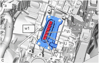
- Check the generator (MG1) for an interphase short using a milliohmmeter.
*a Motor Cable not connected
(Hybrid Vehicle Transaxle Assembly)- Using a milliohmmeter, measure the resistance according to the value(s) in the table below.
HINT:
If the generator (MG1) temperature is high, the resistance will vary greatly from the specification. Therefore, measure the resistance at least 8 hours after the vehicle has been stopped.
Standard Resistance
Tester Connection Condition Specified Condition w1-4 (W) - w1-5 (U) Ignition switch off 25.7 to 28.5 mΩ w1-5 (U) - w1-6 (V) Ignition switch off 25.7 to 28.5 mΩ w1-4 (W) - w1-6 (V) Ignition switch off 25.8 to 28.6 mΩ HINT:
To correct the variation of the measured resistance due to temperature, use the following formula to calculate the resistance at 20°C (68°F).
- R20 = Rt / {1 + 0.00393 X (T - 20)}
The calculation is based on the following:
- R20: Resistance at 20°C (68°F) (mΩ)
- Rt: Measured resistance (mΩ)
- T: Temperature when the resistance is measured (°C)
- Using a milliohmmeter, measure the resistance according to the value(s) in the table below.
- Using a megohmmeter set to 500 V, measure the resistance according to the value(s) in the table below.NOTE:
Be sure to set the megohmmeter to 500 V when performing this test. Using a setting higher than 500 V can result in damage to the component being inspected.
Standard Resistance
Tester Connection Condition Specified Condition w1-4 (W) - Body ground and shield ground Ignition switch off 10 MΩ or higher w1-5 (U) - Body ground and shield ground Ignition switch off 10 MΩ or higher w1-6 (V) - Body ground and shield ground Ignition switch off 10 MΩ or higher - Connect the motor cable.
Result
Proceed to OK NG
Result:
NG
See step 10
Result:
OK
See step 8
- Check that the service plug grip is not installed.
- REPLACE MOTOR CABLE
Refer to REMOVAL [12/2019 - 10/2022] , or refer to REMOVAL [10/2022 - 11/2023]
Result
Proceed to NEXT Result:
NEXT
See step 9
- REPLACE INVERTER WITH CONVERTER ASSEMBLY
Refer to REMOVAL [12/2019 - 10/2022] , or refer to REMOVAL [10/2022 - 11/2023]
Result
Proceed to NEXT Result:
NEXT
See step 13
- REPLACE MOTOR CABLE
Refer to REMOVAL [12/2019 - 10/2022] , or refer to REMOVAL [10/2022 - 11/2023]
Result
Proceed to NEXT Result:
NEXT
See step 11
- REPLACE HYBRID VEHICLE TRANSAXLE ASSEMBLY
Refer to REMOVAL [12/2019 - 10/2022] , or refer to REMOVAL [10/2022 - 11/2023]
Result
Proceed to NEXT Result:
NEXT
See step 12
- REPLACE INVERTER WITH CONVERTER ASSEMBLY
Refer to REMOVAL [12/2019 - 10/2022] , or refer to REMOVAL [10/2022 - 11/2023]
Result
Proceed to NEXT Result:
NEXT
See step 13
- CHECK DTC OUTPUT (MOTOR GENERATOR)
- Check the other DTCs that were output together with DTC P0A7A-73.
Powertrain > Motor Generator > Trouble Codes
Result
Relevant DTC P0A7A-9E Generator Inverter Stuck On P1C5F-19 Generator Inverter Circuit Current Above Threshold NOTE:DTC P0A7A-73 is stored after DTC P0A7A-9E and/or P1C5F-19 is stored. After troubleshooting and repairing the malfunction which caused DTC P0A7A-73 to be stored, be sure to troubleshoot the other DTCs.
Result
Proceed to NEXT
Result:
NEXT
GO TO DTC CHART (MOTOR GENERATOR CONTROL SYSTEM) . Refer to DIAGNOSTIC TROUBLE CODE CHART [12/2019 - 10/2021] , or refer to DIAGNOSTIC TROUBLE CODE CHART [10/2021 - 11/2023]
- Check the other DTCs that were output together with DTC P0A7A-73.