DTC P0A1B-1F: Generator Control Module Circuit Intermittent [12/2019 - 11/2023]: Procedure
- CHECK DTC OUTPUT
- Check for DTCs.
Powertrain > Hybrid Control > Trouble Codes
Powertrain > Motor Generator > Trouble Codes
Result
Result Proceed to P0A1B-1F only is output. A DTCs of hybrid control system in the tables below are output. B DTCs of motor generator control system in the tables below are output. C Malfunction Content System Relevant DTC Communication malfunction Motor generator control system P3124-87 Lost Communication between Drive Motor "A" and HV ECU Missing Message Hybrid control system P3123-87 Lost Communication with Drive Motor Control Module "A" from Hybrid/EV Control Module Missing Message U0110-87 Lost Communication with Drive Motor Control Module "A" Missing Message - Turn the ignition switch off.
Result:
B
GO TO DTC CHART (HYBRID CONTROL SYSTEM)
Refer to DIAGNOSTIC TROUBLE CODE CHART [12/2019 - 09/2020] , or refer to DIAGNOSTIC TROUBLE CODE CHART [09/2020 - 10/2021] , or refer to DIAGNOSTIC TROUBLE CODE CHART [10/2021 - 11/2023]
Result:
C
GO TO DTC CHART (MOTOR GENERATOR CONTROL SYSTEM) . Refer to DIAGNOSTIC TROUBLE CODE CHART [12/2019 - 10/2021] , or refer to DIAGNOSTIC TROUBLE CODE CHART [10/2021 - 11/2023]
Result:
A
See step 2
- Check for DTCs.
- CHECK CONNECTOR CONNECTION CONDITION (INVERTER WITH CONVERTER ASSEMBLY CONNECTOR)
See step 3
Result
Result Proceed to OK A NG (The connector is not connected securely.) B NG (The terminals are not making secure contact or are deformed, or water or foreign matter exists in the connector.) C Result:
B
CONNECT SECURELY
Result:
C
REPAIR OR REPLACE HARNESS OR CONNECTOR
Result:
A
See step 3
- CHECK AUXILIARY BATTERY TERMINAL (CONTACT PROBLEM)
- Check the connection of the auxiliary battery terminal.
OK
The terminal is connected securely and there is no contact problem.
Result
Proceed to OK NG
Result:
NG
CONNECT SECURELY
Result:
OK
See step 4
- Check the connection of the auxiliary battery terminal.
- CHECK HARNESS AND CONNECTOR (INVERTER WITH CONVERTER ASSEMBLY - IGCT RELAY) WARNING:
Be sure to wear insulated gloves.
- Check that the service plug grip is not installed.NOTE:
After removing the service plug grip, do not turn the ignition switch on (READY), unless instructed by the repair information because this may cause a malfunction.
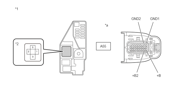
- Disconnect the A55 inverter with converter assembly connector.
- Remove the IGCT relay from the No. 5 floor relay block and No. 5 floor junction block assembly.
- Measure the resistance according to the value(s) in the table below.
*1 No. 5 Floor Relay Block and No. 5 Floor Junction Block Assembly *2 IGCT Relay *a Front view of wire harness connector
(to Inverter with Converter Assembly)- - Standard Resistance
Tester Connection Condition Specified Condition A55-36 (+B) - 5 (IGCT relay) Ignition switch off Below 1 Ω A55-35 (+B2) - 5 (IGCT relay) Ignition switch off Below 1 Ω A55-9 (GND1) - Body ground Ignition switch off Below 1 Ω A55-8 (GND2) - Body ground Ignition switch off Below 1 Ω - Install the IGCT relay.
- Reconnect the A55 inverter with converter assembly connector.
Result
Proceed to OK NG
Result:
NG
REPAIR OR REPLACE HARNESS OR CONNECTOR
Result:
OK
See step 5
- Check that the service plug grip is not installed.
- CHECK FOR INTERMITTENT PROBLEMS
- Check for intermittent problems.
Refer to CHECK FOR INTERMITTENT PROBLEMS [12/2019 - 11/2023]
- Check the connection and terminal contact pressure of the connectors and wire harnesses between the auxiliary battery and the inverter with converter assembly.
Result
There are no abnormalities in the wire harnesses and connectors.
Result
Proceed to OK NG - Check the connection and terminal contact pressure of the connectors and wire harnesses between the auxiliary battery and the inverter with converter assembly.
Result:
OK
REPLACE INVERTER WITH CONVERTER ASSEMBLY
Refer to REMOVAL [12/2019 - 10/2022] , or refer to REMOVAL [10/2022 - 11/2023]
Result:
NG
REPAIR OR REPLACE MALFUNCTIONING PARTS, COMPONENT AND AREA
- Check for intermittent problems.