DTC P1CE2-13: PCU Interlock Circuit Open; DTC P1CE2-92: PCU Interlock Performance or Incorrect Operation [12/2019 - 11/2023]: Procedure
- CHECK DTC OUTPUT (HYBRID CONTROL, MOTOR GENERATOR)
- Check for DTCs.
Powertrain > Hybrid Control > Trouble Codes
Powertrain > Motor Generator > Trouble Codes
Result
Result Proceed to P1CE2-13 or P1CE2-92 only is output, or DTCs except the ones in the table below are also output. A DTCs of Hybrid Control System in the tables below are output. B DTCs of Motor Generator Control System in the tables below are output. C Malfunction Content System Relevant DTC Microcomputer malfunction Hybrid Control System P0606-47 Hybrid/EV Powertrain Control Module Processor Watchdog / Safety MCU Failure P0606-87 Hybrid/EV Powertrain Control Module Processor to Monitoring Processor Missing Message P060A-47 Hybrid/EV Powertrain Control Module Monitoring Processor Watchdog / Safety MCU Failure P060A-87 Hybrid/EV Powertrain Control Module Processor from Monitoring Processor Missing Message P060B-49 Hybrid/EV Powertrain Control Module A/D Processing Internal Electronic Failure P060B-71 Hybrid/EV Powertrain Control Module A/D Processing Actuator Stuck P060B-1C Hybrid/EV Powertrain Control Module A/D Processing Voltage Out of Range P1CE3-49 Hybrid/EV Powertrain Control Module Monitoring Processor A/D Processing Internal Electronic Failure P1CE3-71 Hybrid/EV Powertrain Control Module Monitoring Processor A/D Processing Actuator Stuck P1CE3-1C Hybrid/EV Powertrain Control Module Monitoring Processor A/D Processing Voltage Out of Range P060A-45 Hybrid/EV Powertrain Control Module Monitoring Processor Program Memory Failure P060A-44 Hybrid/EV Powertrain Control Module Monitoring Processor Data Memory Failure P060A-29 Hybrid/EV Powertrain Control Module Monitoring Processor Signal Invalid P060A-49 Hybrid/EV Powertrain Control Module Monitoring Processor Internal Electronic Failure P0A1B-49 Drive Motor "A" Control Module Internal Electronic Failure Motor Generator Control System P0A1B-1F Generator Control Module Circuit Intermittent Power source circuit malfunction Hybrid Control System P0688-1F ECM/PCM Power Relay Sense Circuit Intermittent Communication system malfunction Hybrid Control System P3123-87 Lost Communication with Drive Motor Control Module "A" from Hybrid/EV Control Module Missing Message System malfunction Hybrid Control System P1C9E-9F Hybrid/EV System Reset Stuck Off HINT:
- P1CE2-13 or P1CE2-92 may be output as a result of the malfunction indicated by the DTCs above.
- The chart above is listed in inspection order of priority.
- Check DTCs that are output at the same time by following the listed order. (The main cause of the malfunction can be determined without performing unnecessary inspections.)
- P1CE2-13 or P1CE2-92 may be output as a result of the malfunction indicated by the DTCs above.
- Turn the ignition switch off.
Result:
B
GO TO DTC CHART (HYBRID CONTROL SYSTEM)
Refer to DIAGNOSTIC TROUBLE CODE CHART [12/2019 - 09/2020] , or refer to DIAGNOSTIC TROUBLE CODE CHART [09/2020 - 10/2021] , or refer to DIAGNOSTIC TROUBLE CODE CHART [10/2021 - 11/2023]
Result:
C
GO TO DTC CHART (MOTOR GENERATOR CONTROL SYSTEM) . Refer to DIAGNOSTIC TROUBLE CODE CHART [12/2019 - 10/2021] , or refer to DIAGNOSTIC TROUBLE CODE CHART [10/2021 - 11/2023]
Result:
A
See step 2
- Check for DTCs.
- CLEAR DTC
Refer to PROCEDURE - Step 3
Result
Proceed to NEXT Result:
NEXT
See step 3
- CHECK DTC OUTPUT (HYBRID CONTROL)
- Check if DTCs are output.
Powertrain > Hybrid Control > Trouble Codes
Result
Result Proceed to P1CE2-13 or P1CE2-92 is output again. A Neither P1CE2-13 or P1CE2-92 is output again. B HINT:
Check if the same DTC is output.
- Turn the ignition switch off.
Result:
B
See step 4
Result:
A
See step 4
- Check if DTCs are output.
- CHECK INVERTER COVER WARNING:
Be sure to wear insulated gloves.
- Check that the service plug grip is not installed.NOTE:
After removing the service plug grip, do not turn the ignition switch to ON (READY), unless instructed by the repair information because this may cause a malfunction.
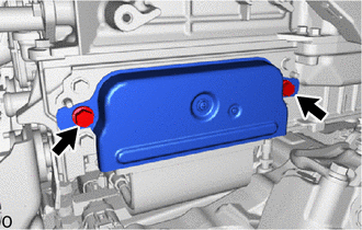
- Check if the inverter cover of the inverter with converter assembly is installed correctly.
OK
The inverter cover is installed correctly.
Result
Proceed to OK NG
Result:
NG
INSTALL PARTS CORRECTLY
Result:
OK
See step 5
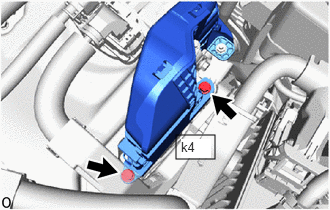
- Check that the service plug grip is not installed.
- CHECK FLOOR UNDER WIRE (REAR TRACTION MOTOR CABLE CONNECTOR INSTALLATION CONDITION) WARNING:
Be sure to wear insulated gloves.
- Check that the service plug grip is not installed.NOTE:
After removing the service plug grip, do not turn the ignition switch to ON (READY), unless instructed by the repair information because this may cause a malfunction.
- Check if the HV floor under wire (rear traction motor cable) is connected correctly.
OK
The HV floor under wire (rear traction motor cable) is connected correctly.
Result
Proceed to OK NG
Result:
NG
INSTALL PARTS CORRECTLY
Result:
OK
See step 6
- Check that the service plug grip is not installed.
- CHECK INVERTER COVER WARNING:
Be sure to wear insulated gloves.
- Check that the service plug grip is not installed.NOTE:
After removing the service plug grip, do not turn the ignition switch to ON (READY), unless instructed by the repair information because this may cause a malfunction.
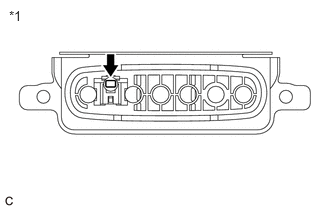
- Remove the inverter cover from the inverter with converter assembly.
Refer to REMOVAL [12/2019 - 10/2022] , or refer to REMOVAL [10/2022 - 11/2023]
- Check the condition of the inverter cover interlock.
OK
Dirt or foreign matter has not entered the connectors and there is no evidence of contamination.
*1 Inverter Cover - Install the inverter cover.
Result
Proceed to OK NG
Result:
NG
REPLACE INVERTER COVER
Refer to REMOVAL [12/2019 - 10/2022] , or refer to REMOVAL [10/2022 - 11/2023]
Result:
OK
See step 7
- Check that the service plug grip is not installed.
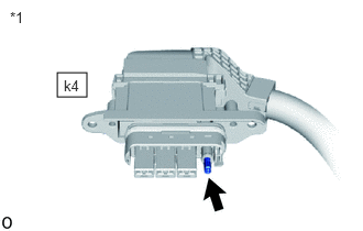
- CHECK FLOOR UNDER WIRE (REAR TRACTION MOTOR CABLE CONNECTOR) WARNING:
Be sure to wear insulated gloves.
- Check that the service plug grip is not installed.NOTE:
After removing the service plug grip, do not turn the ignition switch to ON (READY), unless instructed by the repair information because this may cause a malfunction.
- Disconnect the HV floor under wire (rear traction motor cable) from the inverter with converter assembly.
- Check the condition of HV floor under wire (rear traction motor cable) interlock.
OK
Dirt or foreign matter has not entered the connectors and there is no evidence of contamination.
*1 HV Floor Under Wire (Rear Traction Motor Cable) - Connect the HV floor under wire (rear traction motor cable) to the inverter with converter assembly.
Result
Proceed to OK NG
Result:
OK
REPLACE INVERTER WITH CONVERTER ASSEMBLY
Refer to REMOVAL [12/2019 - 10/2022] , or refer to REMOVAL [10/2022 - 11/2023]
Result:
NG
REPLACE FLOOR UNDER WIRE
- Check that the service plug grip is not installed.